Microphone control board circuit program development
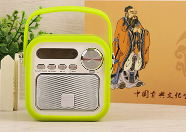
The audio power amplifier circuit module and the single-chip microcomputer control circuit module play a major role in this design. The single-chip microcomputer is mainly used for programming. The analog switch and the digital potentiometer are controlled by the single-chip microcomputer. Using these project modules, the high-quality sound can be realized. Or low, to select the type of input signal, and can also realize the mute function, the main feature is less energy consumption, small size and easy to carry, mainly used in audio, teaching and education, etc.
1. The overall scheme design of the loudspeaker
Option 1: LM358 is used as the op amp for the voice amplifier circuit, the analog switch CD4053 is used for the input signal selection part, the X9319 digital potentiometer is used for the digital volume control part, the audio power amplifier is TDA2003, STC89C51 is used for the MCU control circuit, and the chip 7805 is used for the power supply circuit .
Scheme 2: LM324 is used as the operational amplifier for the voice amplifier circuit, the analog switch CD4051 is used for the input signal selection part, the X9511 digital potentiometer is used for the digital volume control part, the audio power amplifier is TDA2030, AT89C51 single-chip microcomputer is used for the MCU control circuit, and the chip 2575 is used for the power supply circuit .
LM358 is a dual computing chip with 8 pins, and both single and dual power supplies can work. And its price is cheap, and the area of the chip is relatively small. If it is used to amplify the DC signal, it can reach 20HZ. According to the design requirements, it is more appropriate to choose LM358. According to the requirements of the design, it is required to select two signals of voice and audio input, so the analog switch is suitable for digitally controlled analog switches with three or two channels, so the CD4053 chip is selected. Because TDA2003 is a single power supply mode, the output power of TDA2003 is 5W when the impedance is 4Ω, and the output power of TDA2030 is 18W when the impedance is 4Ω, and the wiring method of TDA2003 is relatively simple, so the chip TDA2003 is selected as the audio power amplifier . STC single-chip microcomputer is an enhanced version of 51 single-chip microcomputer, fully compatible with MCS-51, STC89C51 can replace AT89C51, and has stronger functions, better speed, longer life, lower price, STC89C51 can be programmed online, that is, it has ISP function, AT89C51 must pass Programmer burning, the series of 51 single-chip microcomputer chips launched by STC are fully compatible with other 51 single-chip microcomputers. STC89C51 has E2PROM inside, which can be modified in the program, and the data will not be lost when the power is turned off, so the STC89C51 single-chip microcomputer is selected. X9313 has a wide range of applications and is often used, and the circuit structure is simple and easy to debug. As long as there is no error in welding, basically no debugging is needed, so X9313 is selected.
In summary, the first option is better. The voice amplifier circuit adopts LM358 chip, which can amplify the weak signal in the voice input or audio input. It is a dual operational amplifier with high gain and wide voltage. The input signal selection circuit uses an analog switch CD4053, which can select two groups of signals for voice input and audio signal input. The digital control circuit adopts the digital potentiometer X9313. Its working principle is mainly to change the resistance to control its gain, and realize the controllable gain amplifier better. The audio power amplifier circuit adopts the chip TDA2003, which amplifies the input current, and then drives the speaker to emit sound. The power supply circuit uses 18V DC power supply to supply power to the audio power amplifier. After the 7805 chip steps down, it provides about 5V DC power supply for the microcontroller.
2.The design of the loudspeaker circuit
The voice amplifying circuit is composed of a MIC amplifying circuit and a non-directional voltage amplifier. It is powered by a single power supply. The MIC senses the weak vibration of the sound wave in the air and outputs an electrical signal with the same law as the sound. Because the MIC needs a DC bias, it needs Add a capacitor C3 to block the DC to prevent the weakening of the signal. R4 and R5 form a bias circuit with a value of 240KΩ, which can ensure the undistorted amplification of the voice signal. MIC1 and R1, C4 form a MIC amplifier circuit, between 20-30mVpp Between 2-3mA is the output voice voltage and working current of the MIC amplifier circuit. The main measure to filter out high-frequency interference is mainly completed by capacitor C4. Through the above measures, the anti-interference performance of the voice circuit is greatly improved. The LM358 op amp circuit and R, C together form a non-directional voltage amplifier. Since the gain is amplified by more than 50 times, the error must be taken into account, so the value of R7 is 51KΩ, and the value of R9 is 1KΩ. Voice amplifier circuit shown in Figure 2.

The input signal selection circuit is composed of an analog switch CD4053. The control of the analog switch is to switch between the input signal AUDIOI/2 through the TTL logic level, and to realize the selection of the input signal through two sets of input addresses of AB. When inputting AXBX, It is an audio line signal input. When inputting AYBX, it is a voice input signal. When the mute function is required, select BY. Whether it is AXBY or AYBY, the signal is not output. In order to play a good filtering effect, it is necessary to add C7 and C10 in the circuit, in order to protect the chip, it is necessary to add a resistor R8, the specific circuit diagram is shown in Figure 3.

The digital volume control circuit adopts the non-volatile digital potentiometer with built-in EEPRM of X9319W. The timing diagram of the digital potentiometer and the corresponding time parameters are the basis for the programming technology of the single-chip microcomputer to control the digital potentiometer. In the digital volume control circuit, capacitor C11 acts as a filter. R11, R12, C12, and C13 are input circuits, and R11 is a power resistor, which protects the chip. Its value is 3K, and C12 is used to filter out high-frequency interference signals. The measure to prevent self-excited oscillation of the power amplifier circuit is in the circuit Connect a resistor R16 and a capacitor C19 in parallel. In order to increase the output power, the capacity of the output capacitor C18 should be larger. If the designed output power increases, the capacity of the capacitor should also increase. If the capacity of the capacitor is not enough, the output power will be reduced. It will be less than the rated power, and the efficiency of the power amplifier circuit will also be reduced. The negative feedback circuit is composed of R13, which can reduce the input signal. C14 and C15 are the power filter circuit, and R4 and R5 provide DC bias. In order to improve the life of the power amplifier, To install a radiator to assist its cooling. The specific circuit diagram is shown in Figure 4.

The microcontroller control circuit mainly uses STC89C51, and in order to ensure the stability and load capacity of the microcontroller, a pull-up resistor with a resistance value of 4.7-10K should be added to the circuit. It is best to use the exclusion of surface mount technology. In order to better display the running status of the single-chip microcomputer and display the progress of the program in the debugging program, more than one LED should be added to analyze the problems existing in the program. The MIC control circuit diagram is shown in Figure 5.

Since there are analog circuits and digital circuits on the circuit, in order to improve the anti-interference ability of the signal part on the circuit board, two power outputs are used, one is to use 7805 digital power supply, and the other is to use 78L05 analog power supply alone For power supply, in order to prevent students from burning out the IC by connecting the input power reversely, it is necessary to install a polar diode at the input end of the power supply for protection. When the power consumption is small, the regulator does not need to install a radiator. When the power consumption is large, the regulator needs to install a radiator or a power resistor at the input end to assist heat dissipation. In this circuit, since its power consumption Pc= (ViVo). Io is less than 0.3W, so there is no need to install a radiator or power resistor.
Summarize
Digital volume control loudspeaker circuit, the system hardware circuit includes 6 parts: voice amplifier circuit, input signal selection circuit, digital volume control circuit, audio power amplifier circuit, MCU control circuit, power supply. The power supply circuit supplies power to the entire system, the voice amplifier circuit amplifies the input sound, the input signal selection circuit selects two groups of input signals, the voice input and the audio signal input, the digital volume control circuit controls the gain of the amplifier, and the audio power amplifier circuit The input current signal is amplified to drive the speaker. The MCU control circuit is the backbone of the design of the digital volume control loudspeaker. The audio power amplifier is controlled by the program to realize the increase and decrease of the volume and the mute control.
The above is the design and development example of the digital volume control loudspeaker circuit introduced by Shenzhen Zuchuang Microelectronics Co., Ltd. for you. If you have a need for amplifier circuit board solution development, you can trust us. We represent a variety of single-chip microcomputers, voice chips, dual-mode Bluetooth ICs, and wifi chips. Brands include Songhan MCU, Yingguang MCU, Jerry Bluetooth, Ankai Bluetooth, Allwinner, and Realtek. Our technical services include: PCB design, MCU development, Bluetooth solution, software and hardware custom development, APP development, small program development, WeChat official account development, etc. It can also undertake the design of intelligent electronic products, the development of living appliances, the research and development of beauty equipment, the application of Internet of things platform, the smart home control system, the development of TWS earphones, Bluetooth earphone speakers, the development of children's educational toys, the design of electronic education products, etc.
Proposal recommendation
- TOP


