- Home >> Solution >> Appliances >> home appliances
Heater program
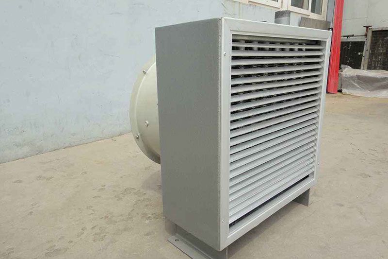
With the improvement of power supply and the continuous improvement of people's living standards, heaters have gradually entered ordinary families, bringing strong warmth to consumers in the middle of winter. However, most heaters do not have a good human-computer interaction interface and remote control function. This design mainly studies this part, so that the heater can use the liquid crystal display to display the real-time working display temperature, and use the infrared remote controller to remotely control the heater. Make products more competitive in the market and bring more convenience to people.
1. Composition of the heater program system
As shown in Figure 1, the system consists of five parts: MCU main controller, keyboard and liquid crystal display, infrared input, temperature detection and output controller.
The main modules are as follows: (1) Keyboard and liquid crystal display module. This module is responsible for starting and shutting down the system, and at the same time controlling the upper limit of the working temperature of the heater, setting the working time of the heater, and controlling the shaking head and the fan. The LCD screen displays the ambient temperature of the system, the set temperature and time, etc. (2) Infrared input module. The module uses the infrared integrated receiver to decode and analyze the instructions through the single-chip microcomputer. (3) Temperature detection module. This module uses the thermistor to measure the resistance to calculate the temperature, so as to prevent the system from overheating and damage the equipment. (4) Control the output module. This module is the relay corresponding to the corresponding level control of the I/O port output.

2. Design scheme of remote control heater
The dot matrix of the LCD is relatively large. If the I/O of the single-chip microcomputer is directly driven by the bias voltage of the resistor network, the I/O operation of the single-chip microcomputer will be very cumbersome. Here we choose a commonly used chip HT1621. The HT1621 is a 128-point memory image and multi-function LCD driver. The software configuration feature of the HT1621 makes it suitable for a variety of LCD applications, including LCD modules and display subsystems.
2.1 Display Controller
The liquid crystal display controller is the display part of the multifunctional automatic intelligent switch, which can monitor the operation of the power supply line in real time, accurately and online. Once leakage, overload, short circuit, overvoltage, undervoltage and phase loss occur in the line, the intelligent safety switch can immediately start the protection program and display it on the HT1621 LCD controller. The main controller and the HT1621 chip are connected according to the conventional pins, and the oscillator can use the internal oscillator of the HT1621 without external connection. LCD is used to display content, it only needs to write signal and there is no read signal.
2.2 Temperature detection technology
Heaters often work under high temperature conditions, and the possibility of damage to devices due to overheating is very high, so the system must be checked at all times. The ambient temperature and device temperature are input to the microcontroller in the form of numerical values through the I/O port, and the microcontroller processes these numerical values with special significance, and then sends instructions. If the single-chip microcomputer used does not have an A/D converter, the single-chip microcomputer cannot obtain the resistance value of the thermistor used to measure the operating temperature of the heater. If the system does not have high requirements on the accuracy of A/D conversion, considering the cost, the RC circuit can be used to measure the resistance through the length of its charging time. The RC circuit is powered by the I/O port of the microcontroller. This method is generally used on single-chip microcomputers with push-pull I/O ports. Close the switch, the power supply charges the capacitor C through R. Use the I/O port of the single chip microcomputer to charge the standard resistance and the resistance to be tested. When the voltage reaches the high level threshold of the I/O port, record their charging time, and the resistance value can be obtained through the corresponding calculation formula, and the charging time It can be obtained by using the timer of the single-chip microcomputer.

2.3 Microcontroller
As the main control unit of the system, the single-chip microcomputer controls all input and output, and adjusts the air supply mode and temperature of the heater according to the user's button information. In this design, AT89S51 is selected, which is a low power consumption, high performance CMOS 8-bit microcontroller. In addition, AT89S51 is designed and configured with an oscillation frequency of 0Hz and a power-saving mode that can be set by software. In idle mode, CPU suspends work, while RAM timer counter, serial port, and external interrupt system can continue to work. In power-down mode, the oscillator is frozen to save RAM data, and other functions of the chip are stopped until external interrupt activation or hardware reset.
2.4 Infrared remote control system
The general infrared remote control system consists of two parts: transmitting and receiving. Application code/decode special integrated circuit chip for control operation, the transmitting part includes keyboard matrix, code modulation, LED infrared transmitter; the receiving part includes optical and electrical conversion amplifier, demodulation and decoding circuit. The receiving circuit can use an integrated infrared receiver that integrates infrared reception and amplification. It does not need any external components to complete all the work from infrared reception to output compatible with TTL level signals, and the volume and ordinary plastic package The size of the triode is the same, it is suitable for various infrared remote control and infrared data transmission.
3. The hardware design of the heater
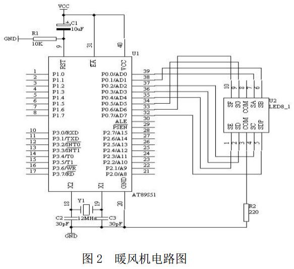
The overall circuit of the system is divided according to the actual circuit function: button detection circuit, infrared detection and HT1621 data circuit and relay control circuit. See Figure 2 for the circuit diagram of the heater. Test the environment and the operating temperature of the device to ensure that the device works under normal working conditions. This process is detected by the microcontroller, and then the corresponding steps are taken when the corresponding conditions are triggered.

3.1 Button detection circuit
The key detection circuit includes: 6 contact buttons, the connected case is used to adjust the temperature of the heater, one for heating and one for cooling; the connected buttons are TIME (display time) and HEAT (heating wire heating); the connected buttons of P64 are Air supply speed, one of which is accelerated and the other is decelerated; 3 current-limiting resistors have a resistance value of 100 ohms; 3V high-level power supply is provided by the system power supply. The MCU uses 3 I/O ports to collect button information, and each port is connected to 2 buttons. Because the single-chip microcomputer AT89S51 first sets the I/O port as an internal pull-up input, then the button pulled to the ground can be detected; and then the I/O port is set as an internal pull-down input, then the button pulled to the power supply can be detected. In order to prevent the two buttons from being pressed at the same time and cause a short circuit, a small resistor is connected in series between the two buttons and the power supply.
3.2 Infrared detection
Infrared detection and HT1621 multiplex MCU port, its circuit composition includes: RN, adjustable port resistance, the maximum resistance value is 10k; RF, infrared detection port resistance, resistance value is 10k; AC filter capacitor is 1uF; P60 and P61 ports It is the multiplexed I/O port of the infrared detection input and the DATA line of the HT1621. In order to prevent the data received by the infrared from interfering with the communication between the microcontroller and the HT1621, the infrared input part is connected in series with resistors RF and RN. RN is an adjustable resistor, because P60 is also an external interrupt input port and needs to be adjusted to an appropriate resistance value. In this design, RN can maintain the same resistance value as RF.
3.3 Output control circuit
The output control circuit mainly includes fan switch control, shaking head switch control and heating switch control. This module is the relay corresponding to the corresponding level control of the I/O output.
Summarize
The above are the details of the heater solution introduced by Shenzhen Zuchuang Microelectronics Co., Ltd. for you. If you have the electronic function development needs of the heater, you can rest assured to entrust it to us. We have rich experience in custom development of electronic products, and can evaluate the development cycle and IC price as soon as possible, and can also calculate the PCBA quotation. We are a number of chip agents at home and abroad: Songhan, Yingguang, Jieli, Ankai, Quanzhi, realtek, with MCU, voice IC, Bluetooth IC and module, wifi module. Our development capabilities cover PCB design, single-chip microcomputer development, Bluetooth technology development, software customization development, APP customization development, WeChat official account development and other hardware and software design. It can also undertake the research and development of smart electronic products, the design of household appliances, the development of beauty equipment, the development of Internet of Things applications, the design of smart home solutions, the development of TWS earphones, the development of Bluetooth earphone speakers, the development of children's toys, and the development of electronic education products.
- TOP
