USB dongle solution development
The dongle is a software protection device connected to the computer port. It includes a host check program and a key (also called an encryption box). It is an encryption technology that combines software and hardware. It has the characteristics of strong encryption and high reliability. It is now widely used in computer software protection. Dongle technology has developed to the fourth generation. It uses USB interface, microcontroller and EEPROM as core devices, also known as micro-dog. It has been greatly improved in terms of intelligence, application flexibility and anti-cracking capabilities.
There are three ways to implement a USB dongle: One is the simplest, which does not require encryption and only returns confirmation information, that is, the computer sends data to the dongle, and after receiving the data, the dongle verifies whether it is correct and returns a confirmation message to the computer. The second is to encrypt the data, that is, the computer sends the data to the dongle, and the dongle processes the received data according to a certain algorithm. At the same time, the dongle returns the processed data to the host computer, and the host computer verifies the encrypted data. The above two methods simply implement the function of the dongle. Although there is also encryption processing, the data is transmitted in clear code through the USB interface, and it is easy to be cracked by data monitoring software on the computer after obtaining the data. The third is the multiple encryption method, that is, the data transmission process is encrypted again.
The current popular USB dongle design solution is microcontroller + USB interface chip + EEPROM memory. This solution is not only complex in system, but also has shortcomings such as large size and high hardware cost. The selected design solution is to use a microcontroller with an internal EEPROM to simulate USB timing through ordinary IO ports, complete USB1.1 protocol communication, use the DES algorithm to achieve confidential transmission and data encryption, and finally realize the function of the USB dongle. That is, the problem can be solved with a single chip.
1. Hardware design of USB dongle
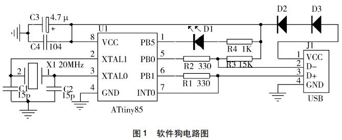
The hardware circuit diagram used by the USB dongle is shown in Figure 1. All functions are completed by one chip, which not only reduces the hardware cost but also improves the system reliability. The microcontroller selected in the circuit is ATtiny85 produced by Atmel. It is an 8-bit microcontroller based on AVRRISC low-power CMOS, with an operating voltage of 1.8~5.5V, embedded 8K bytes of Flash program memory, and 512 bytes of SRAM. Data memory and 512 bytes of EEPROM, its Flash program memory supports ISP and debugWIR programming. It adopts SOP8 package and has 6 multi-function multiplexed I/O pins, all of which can be configured as external interrupts. There are 2 independent 8-bit timer/counters that can set the prescaler. It also integrates a power-on reset circuit, a watchdog, an RC oscillator, and an on-chip temperature sensor. As shown in Figure 1, the 5V voltage introduced from the USB interface becomes a 3.6V voltage after being stepped down by two diodes and is used as a system power supply for the microcontroller. Configure the 1st pin of the microcontroller as an IO port to connect to an external LED to display the operating status. The 5th and 6th pins are configured as IO ports to connect to the USB data line. The 7th pin is configured as an external interrupt pin. In order to meet the 1.5M speed timing read and write requirements of low-speed USB devices, the microcontroller needs to reach an instruction execution speed of 20MIPS, so pins 2 and 3 are configured as crystal oscillator pins in the circuit and connected to a 20MHz crystal oscillator.

According to the USB protocol specification, the downstream ports D+ and D- of the USB host are each connected to a 15K pull-down resistor to ground. When the port is floating (that is, no device is inserted), the input terminal is pulled back to low by the two pull-down resistors. level. On the USB device side, a 1.5K pull-up resistor is connected to D+ or D- to the power supply. Whether the 1.5K pull-up resistor is connected to D+ or D- is determined by the speed of the USB device. The pull-up resistors for full-speed devices and high-speed devices are connected to D+, while the pull-up resistors for low-speed devices are connected to D-. When the device is plugged into the downstream port of the USB host, the voltage of the data line connected to the pull-up resistor is determined by the voltage division of the 1.5K pull-up resistor and the 15K pull-down resistor. A high-level signal is generated, and the USB host controller can It is detected whether the data line being pulled high is D+ or D- to determine what speed type device is plugged in. Because the dongle designed in this solution is a low-speed USB device, the pull-up resistor R3 of the differential data line D- of the USB interface is 1.5K. At the same time, D- is connected to the PB0 pin of the microcontroller ATtiny85 through the 330Ω current-limiting resistor R2. The PB1 pin is connected to D+ and INT0 through the resistor R1. INT0 is the external interrupt port of the microcontroller. When there is data on the USB bus, it is triggered by an interrupt. . Since the D- level will not jump when the bus is in the recovery state and reset signal state, the D+ data line needs to be connected to the external interrupt 0 (INT0) of the microcontroller. When an interrupt occurs, it means that there is data transmission on the bus. , at this time, the software will determine what kind of data is to be transmitted.
2. Implementation of dongle USB interface
Use the IO port of the microcontroller to simulate the USB interface timing to complete the functions of the USB interface chip, including NRZI encoding and decoding, synchronization mode recognition, parallel/serial conversion, bit filling/unfilling, CRC verification/generation, and PID verification / generation, address recognition, and handshake evaluation and generation functions. The core of its design is NRZI encoding and decoding of USB data transmission, analysis and descriptor of USB data packets.
The encoding method of USB sending data adopts NRZI encoding: when the data is 0, the level is flipped; when the data is 1, the level is not flipped. In order to prevent the level from changing for a long time, all data are serialized before sending. Later, bit filling processing was added, that is, when 6 consecutive data 1s are encountered, a data 0 is forcibly inserted. The data after bit filling is NRZI encoded and sent to the USB differential data line. The process of USB receiving data is the reverse process of USB sending data: NRZI decoding is performed first, bit stuffing is removed, and finally serial data is converted to parallel data. Because the USB receiver can only obtain the synchronous clock through the USB data packet, there is a synchronization field (SYNC) at the beginning of each USB data packet. The fixed value of this field is 00000001. After this field is encoded by NRZI, it is a For serial square waves, the receiver can synchronize subsequent data signals through the SYNC field. Because the communication process has very strict timing requirements, the software part of this design is written in assembly language, and at the same time select appropriate instructions to meet the timing requirements when performing read and write operations.
The data transmitted on the USB bus is based on packets. A package is divided into different domains, and the domains contained in different types of packages are different. But different packages have a common feature, that is, they all start with SYNC followed by a package identifier (PID), and finally end the package with the package end character EOP. After receiving the EOP end character, the microcontroller begins to analyze the USB data packet to determine the type of the packet and calls the corresponding function to process it.
There are 5 types of USB descriptors for standard USB devices: device descriptor, configuration descriptor, string descriptor, interface descriptor and endpoint descriptor. A USB device has only one device descriptor, which determines how many configurations the device has, and each configuration has a corresponding configuration descriptor; at the same time, the configuration descriptor defines how many interfaces there are in the configuration. Each interface has a corresponding interface descriptor; the interface descriptor defines how many endpoints the interface has, and each endpoint has a corresponding endpoint descriptor; the endpoint descriptor defines the size and type of the endpoint, and so on. In the USB protocol specification, there is no such type as USB dongle, so the class code in the device descriptor is 0XFF, which is a manufacturer-defined device. Considering the actual requirements of the dongle, this design only provides an ordinary data port, which only supports interrupt transmission, and the length of the supported packet is 8 bytes.
Use software to simulate USB timing, realize USB interface communication and enumerate successfully, the interface functions provided to the function program of the upper layer dongle are ReadSoftdogData and WriteSoftdogData, read the 64-bit data sent by the host computer software through the function ReadSoftdogData using software interrupts number, and then return the data to the host computer through the function WriteSoftdogData.
3. Encryption processing method
Considering the security of the equipment and the performance of the single-chip microcomputer in the design, the DES encryption algorithm is adopted. So far, except for using the exhaustive search method to attack the DES algorithm, no other more effective method has been found, so the DES algorithm has extremely high security. The DES algorithm uses a 64-bit key, of which only 56 bits are valid, and the exhaustive space of a 56-bit long key is 256. The encryption flow chart of the DES algorithm is shown in Figure 2. The DES decryption process is similar to the encryption process, and will not be introduced in this article.
The specific process of dongle encryption in this design is shown in Figure 3. The host computer generates a random number D1, and encrypts the random number into D2 and sends it to the USB dongle, that is, to realize the encryption of transmission. After receiving the data D2, the dongle decrypts the data into D1 according to the agreed key. Then another set of encryption is performed on the data to turn the data into D3, and then the transmission encryption is turned into D4, and finally D4 is returned to the computer. After the computer obtains the data D4, it decrypts twice to obtain the data D1, and completes the confirmation function of the dongle. This two-level encryption method effectively prevents the behavior of obtaining passwords through data monitoring software.
4. Implementation of USB dongle function
The function of this dongle is to protect the software copyright. When the user purchases the software from the software supplier, the supplier will write the relevant information of the dongle into the dongle, such as the initial password, the number of computers supported, and the number of computers that the software can use. times and so on. These information can all be stored in the EEPROM in the chip of the one-chip computer through encryption algorithm. When the user is running the software, the dongle will update the information stored in the EEP-ROM according to the usage. The specific functional flow is shown in Figure 4: 1) the enumeration of the dongle device is completed after the USB is inserted; 2) after the enumeration is successful, the host computer software generates a group of 32-bit random numbers, and sends this group randomly through the USB to Dongle; 3) After receiving the 32-bit random number sent by the host computer, the dongle operates on the random number according to the agreed encryption algorithm, and returns the result to the host computer software; 4) After the host computer software receives the data, Also run the encrypted anti-running algorithm to see if the original random number can be returned. If the original random number is successfully returned, the dongle is legal, so as to achieve the purpose of protecting the software copyright.
5. Dongle security performance test
Mainly use USB protocol analysis software USBlyzer, DES encryption and decryption software IDES_Tool and an application software designed by the author to test together. USBlyzer is a USB protocol analysis software. This software can monitor USB interface data in real time. It has functions such as packet capture, unpacketization, and protocol analysis. to the dongle type and device name.
Summarize
This design is based on a single chip as a solution, and the design is simplified from the software. Use software to realize hardware functions, realize confidential transmission through DES encryption algorithm, achieve cost reduction, improve system reliability and security requirements, and provide an ideal way for software copyright protection. Because there is EEPROM inside, it can be used for secondary development for software providers and even users.
The above is an example of the design and development of the USB dongle for the single-chip solution introduced by Shenzhen Zuchuang Microelectronics Co., Ltd. If you have USB dongle control board development needs, you can trust us. We represent a variety of single-chip microcomputers, voice chips, dual-mode Bluetooth ICs, and wifi chips. Brands include Songhan MCU, Yingguang MCU, Jerry Bluetooth, Ankai Bluetooth, Allwinner, and Realtek. Our technical services include: PCB design, MCU development, Bluetooth solution, software and hardware custom development, APP development, small program development, WeChat official account development, etc. It can also undertake the design of intelligent electronic products, the development of living appliances, the research and development of beauty equipment, the application of Internet of things platform, the smart home control system, the development of TWS earphones, Bluetooth earphone speakers, the development of children's educational toys, the design of electronic education products, etc.
Proposal recommendation
- TOP


