Development of constant temperature electric soldering iron control board scheme
Soldering iron is a tool widely used in industries such as electronic product manufacturing and service. With the development of technology, the automatic welding technology of electronic products is also developing continuously, but the use of electric soldering iron for manual welding and desoldering of components is still indispensable. Nowadays, electric soldering irons generally realize functions such as constant temperature control and leakage protection, and the service life is also greatly increased. After the daily use of the electric soldering iron is over, its residual temperature is still relatively high, and it may burn people if you are not careful, and even cause dangerous accidents such as fire. Many people who use electric irons are accustomed to approaching the tip of the soldering iron with their hands to sense the residual temperature of the electric soldering iron, which also poses a risk of burns. In order to allow users to intuitively understand the cooling state of the soldering iron after use, and to avoid possible dangers and possible fire hazards caused by sensing the residual temperature of the soldering iron by hand, an electric soldering iron with a cooling indicator function is designed.
1. Analysis of the working principle of the original electric contact iron
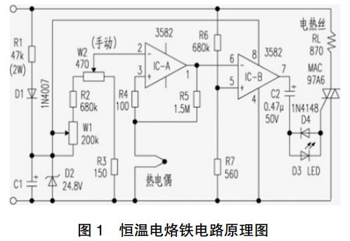
The following is the working principle and circuit diagram of a constant temperature electric soldering iron (see Figure 1). The mains AC220V is stepped down by R1, half-wave rectified by D1, filtered by C1, and stabilized by D2, and then used as the power supply voltage and temperature adjustment setting voltage source of the integrated operational amplifier 3582 comparator IC.

The thermocouple is used as a temperature sensor to detect the tip of the soldering iron, and generates different electromotive force according to the temperature. During the work, the electromotive force is added to the pin ③ of IC-A through the resistor R3, which is used as the input terminal of the thermocouple detection voltage; and the pin ② is the temperature setting voltage. After comparing the voltages at both ends of pin ② and pin ③, it is output by pin ①. The function of the feedback resistor R5 is to lock the output signal unchanged when the input signal fluctuates slightly. When the thermocouple detects that the temperature is low, the level of the ③ pin is lower than that of the ② pin, so that the output of the ① pin is low. Then make the IC-B amplifier ⑥ pin lower than the fixed bias ⑤ pin, so that the output ⑦ pin is high. Since the IC-B ⑤ pin voltage is obtained by dividing the voltage of AC220V through R6 and R7, the frequency and phase are exactly the same as those of AC220V. After comparing the level of ⑤ pin with the level of ⑥ pin, the AC voltage is output on ⑦ pin. The AC voltage controls the bidirectional thyristor through the trigger circuit connected in reverse parallel with C2 and D3 and D4 (acting as a bidirectional diode), and controls the conduction time of the current applied to the heating wire of the soldering iron, so as to achieve the purpose of constant temperature control.
2. Improved design of electric iron control circuit
2.1 Improve the basic idea
The above-mentioned original constant temperature electric soldering iron is improved, and the residual temperature detection is realized by using the thermoelectric effect of the thermocouple in the circuit. While disconnecting the heating control main circuit of the electric soldering iron, lead the voltage signal of the thermocouple to a voltage comparator composed of an integrated operational amplifier. When the cooling of the soldering iron is not over, the output voltage of the thermocouple makes the integrated op amp output a high level, and the LED is lit to indicate that the soldering iron is cooling; when the cooling of the soldering iron is over, the output voltage of the thermocouple is very small, and the integrated op amp The output terminal outputs a low level, and the LED light goes out, indicating that the cooling of the soldering iron is over.
Through the detection of the output voltage of the thermocouple, the LED light can be used to display the temperature state, so that the electric soldering iron has a cooling indication function.
2.2 Specific implementation process
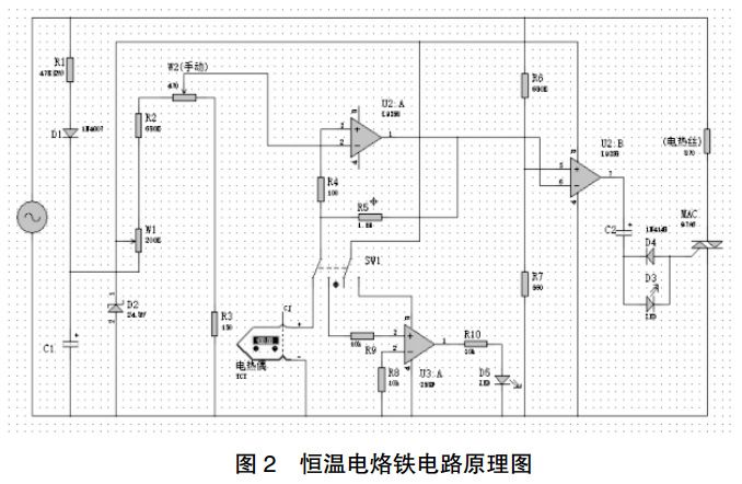
The following is the working principle and circuit diagram of the constant temperature electric soldering iron with cooling indication (see Figure 2). Use the switch SW1 to realize the control of the electric soldering iron working and power-off. When the switch SW1 is closed, the electric soldering iron works normally, and its principle is exactly the same as that of the above circuit, the difference is that after the welding is finished.

After welding is completed, switch SW1 is turned on. U2: pin A③ is disconnected from the thermocouple, so that the output of pin U2: A① is high, and then pin U2: B amplifier ⑥ is higher than pin U2: B ⑤ with fixed bias, so that the output of pin U2: B ⑦ is always low . The triac is off, the heating wire is powered off, and the soldering iron does not work. While the U2: A3 foot branch is disconnected from the thermocouple, the double-throw switch SW1 connects the thermocouple to the U3: A3 foot, and at the same time connects the integrated operational amplifier U3:A power supply ⑧ to the power line, U3:A Start to work, and when the cooling of the soldering iron is not completed, the output voltage of the thermocouple makes the voltage of U3: A③ pin higher than the voltage of ② pin, so that U3: A① pin outputs a high level, and the LED is lit after passing through the current limiting resistor R10; When the temperature of the soldering iron tip drops to the set temperature, the output voltage of the thermocouple makes the voltage of U3:A ③ pin lower than that of ② pin, and then U3:A ① pin outputs a low level, and the LED light D5 goes out, thus starting Cooling indicator function.
3. The actual use effect test of the electric soldering iron
When you want to use the electric soldering iron, turn on the switch, the electric soldering iron is energized, the red power indicator light is on, the electric soldering iron starts heating, and realizes constant temperature control; at the end of use, turn off the switch, the electric soldering iron is powered off, and the power indicator light goes out; at the same time , the blue cooling indicator light is on, and the soldering iron is in the cooling state; when the blue cooling indicator light is off, it means that the cooling of the soldering iron is complete. Figure 3 to Figure 5 are illustrations of actual use effects.
(1) When working normally: When starting to use, press the switch, and the electric soldering iron starts to work. The red power indicator light is on.
(2) Just after use: After use, turn on the control switch, the electric heating wire of the electric soldering iron stops working, and the red power indicator light goes out; the electric soldering iron is in a cooling state, and the blue cooling indicator light is on.
(3) After the soldering iron is cooled: When the blue cooling indicator light goes out, it means that the cooling of the soldering iron is completed.
Summarize
(1) This article improves on the original constant temperature electric soldering iron control circuit, and adds new functions of switch power-off function and cooling indication. From the circuit simulation and physical inspection, it shows that this work can realize the corresponding functions without affecting the temperature. The electric iron uses performance indicators such as power and insulation resistance. The circuit is improved and innovated on the basis of mature circuits, which is scientific and innovative.
(2) On the basis of the design control circuit, only a small amount of components are added to realize its new functions. The following components are mainly used: one operational amplifier LM358, one key switch, one LED light, and three 10k resistors. The devices used are all mature and general-purpose devices on the market, and the increased cost does not exceed 1 yuan. (3) This design improves the use efficiency of the electric soldering iron. This design has the advantages of novel circuit design, practical functions, high reliability, and low cost, and is of great promotion and application value.
The above is an example of the design and development of the constant temperature electric soldering iron with cooling indication function introduced by Shenzhen Zuchuang Microelectronics Co., Ltd. If you have soldering iron PCBA design and development needs, you can trust us. We represent a variety of single-chip microcomputers, voice chips, dual-mode Bluetooth ICs, and wifi chips. Brands include Songhan MCU, Yingguang MCU, Jerry Bluetooth, Ankai Bluetooth, Allwinner, and Realtek. Our technical services include: PCB design, MCU development, Bluetooth solution, software and hardware custom development, APP development, small program development, WeChat official account development, etc. It can also undertake the design of intelligent electronic products, the development of living appliances, the research and development of beauty equipment, the application of Internet of things platform, the smart home control system, the development of TWS earphones, Bluetooth earphone speakers, the development of children's educational toys, the design of electronic education products, etc.
Proposal recommendation
- TOP


