Solar charging wireless mouse design
Compared with the traditional wired mouse, the unfettered wireless mouse has become the choice of more and more people to buy a mouse, and the easier control brings users a comfortable experience. As energy issues and environmental issues are increasingly attracting people's attention, the use of solar energy as a power supply has a high coverage rate without pollution. In our daily life, we are basically under the sun's rays, which provides a steady stream of energy.
In this paper, the solar panel is used as the internal energy supply, and the lithium battery is used as the internal energy storage element. The lithium battery can be charged and used repeatedly, which reduces the cost of battery replacement and the heavy metal pollution that will occur after abandonment, and designs it in the simplest way. Solar charging technology, power display, and overcharge protection are integrated on the wireless mouse, thus making good use of solar energy, and the design direction is in line with the energy-saving concept advocated now.
1. Wireless mouse hardware circuit design
The hardware circuit of solar wireless charging is composed of solar panel, power management circuit, lithium battery, voltage regulator circuit, mouse and display circuit based on single-chip microcomputer control.
(1) Selection of solar panels: 5V2W monocrystalline silicon solar PET panels are selected. The working current is 400MA. Such a large working current can ensure that there will still be a relatively good charging effect even in the case of insufficient light.
(2) Lithium battery selection: The battery part adopts 4.2V1000MAH lithium battery, which provides stable battery life with large capacity, and can output stable voltage to the control chip and display screen through the boost circuit. Lithium batteries can be recycled, which is in line with the concept of using green energy and reducing the pollution of waste batteries.
(3) Choice of power management chip: The chip of power management circuit adopts TP4056. The TP4056 is a complete constant voltage linear charger for single-cell Li-ion batteries.
Its SOP8 package with heat sink on the bottom and fewer external components make TP4056 an ideal choice for portable applications. At the same time, TP4056 can also be suitable for USB power supply and adapter power supply. No external blocking diodes are required due to the internal PMOSFET architecture, coupled with anti-kickback circuitry. Thermal feedback automatically adjusts the charge current to limit the chip during high power operation or high temperature environments. The charging voltage is fixed at 4.2V, while the charging current can be programmed externally with a single resistor.
(4) Selection of the voltage stabilizing circuit: The voltage stabilizing circuit adopts a 5V voltage stabilizing module circuit, so that the battery can provide a low voltage regulator to 5V and then output it to the single chip microcomputer and the display screen. At the same time, a part of the power supply is regulated by the AMS1117 voltage regulator chip, and then outputs 1.5V power to the mouse.
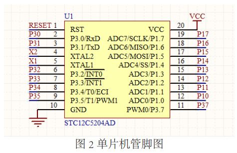
(5) Selection of single-chip microcomputer: In the design of the solar charging wireless mouse, the STC12C5204AD chip is used as the microcontroller. STC12C5204AD is a chip with low power consumption and high performance. The instruction code is fully compatible with the traditional 51 single-chip microcomputer. It is powerful, easy to develop and rich in resources.
The STC12C5204AD microcontroller pins are shown in Figure 2. Among them, pin 20 is the power supply pin, which is connected to the 5V voltage output by the voltage regulator circuit, and pin 10 is the ground pin. Pin 1 is a reset pin for system reset function. Pin 4 and pin 5 are external crystal oscillator pins, which are used to drive the microcontroller and display screen. Pin 8 and pin 9 are timer interrupt pins. This design uses these two pins to detect the level status of the power management chip to determine whether the system is charging or fully charged. Pins 11 to 15 are AD conversion pins. These 5 I/O ports are used here to control the state of the display system.

(6) Selection of display screen: ST7585 with 66×102 pixel dot matrix is selected for the display screen. ST7585 has the advantages of small size and easy to drive. ST7585 is an LCD for graphic dot matrix liquid crystal display. It contains 66×102 pixels and common driving circuits. The chip is directly connected to the processor, requiring only 5 I/O ports for control.
The first pin of ST7585 is the ground pin, pin 2 and pin 3 are power pins, which can be connected to 5V and 3.3V voltage to drive the display screen respectively, this design uses 5V voltage power supply, so connect pin 2 to the circuit Go, pin 3 is empty, pin 5 is the reset pin of the display screen, works on the rising edge, and is used for display initialization, pin 6 SCL pin and pin 9 SDA pin constitute the I2C bus interface, pin 7 and pin 8 are for the display screen Read and write pins. This design uses single-chip microcomputer P11 ~ P15 pins to control the display screen to display battery power and charging status.
(7) The choice of mouse: With the development of computer peripherals, most of them are developing in the direction of wireless, energy saving and more efficiency. The sensitivity of the mouse is also getting higher and higher, and the functions are more diversified. There are functions such as automatically entering sleep mode and manually adjusting the appropriate DPI if it is not used for a long time. Considering that the wireless mouse technology on the market is quite mature now, in order to simplify the design difficulty and reduce the development time, this solution adopts the finished product of the wireless mouse powered by a single dry battery that is convenient to buy on the market, and transforms its power supply part , add the function of solar charging to the mouse.
2. Software design of solar charging mouse microcontroller
The software program design of the single-chip microcomputer mainly completes the following work.
(1) Initialization: After the system starts, it starts initialization. The initialization content includes: (1) Initialization of the timer, turning on the interrupt flag, and the working mode of timer 0 is mode 1, which is convenient and accurate to detect the level status of the power management chip to judge Whether the system is charging or fully charged. (2) The serial port is initialized, and the baud rate is set to the crystal oscillator frequency of 11.0592M, which is convenient for driving the single-chip microcomputer and the display screen.
(2) Determine whether the solar panel is charging the lithium battery by detecting the power management chip: When the input voltage is greater than the low voltage detection threshold of the power supply and the chip enable input terminal is connected to a high level, the TP4056 starts to charge the battery, and the CHRG pin outputs a low power Flat, indicating charging is in progress.
(1) If the battery voltage is lower than 3V, the charging chip precharges the battery with a small current. (2) When the battery voltage exceeds 3V, the charging chip uses constant current mode to charge the battery, and the charging current is determined by the resistance RPROG between the PROG pin and the GND pin. (3) When the battery voltage is close to 4.2V, the charging current gradually decreases, and the chip enters the constant voltage charging mode. When the charging current decreases to the charging end threshold, the charging cycle ends, the CHRG terminal outputs a high-impedance state, and the STDBY terminal outputs a low potential.
(3) Real-time detection of the current battery power: When the MCU communicates with the ST7585 through the serial port, combined with timing interrupts to sample the battery voltage, the current 0-100% power value will be displayed on the ST7585. Thereby, the power management chip is detected again to determine whether the solar panel is charging the lithium battery, and the cycle goes on like this to realize solar energy charging the lithium battery of the wireless mouse.
Summarize
Through overall design, hardware design, software design and software and hardware testing, the design of wireless mouse based on solar charging is finally completed. Solar energy is a new type of green energy, which widely exists in every corner of life. Using solar energy as a mouse The rechargeable power supply is used to replace the dry battery for power supply, which has the significance of environmental protection and energy saving.
The above is the development example of solar rechargeable wireless mouse introduced by Shenzhen Zuchuang Microelectronics Co., Ltd. for you. If you have wireless mouse solution development needs, you can trust us. We represent a variety of single-chip microcomputers, voice chips, dual-mode Bluetooth ICs, and wifi chips. Brands include Songhan MCU, Yingguang MCU, Jerry Bluetooth, Ankai Bluetooth, Allwinner, and Realtek. Our technical services include: PCB design, microcontroller development, Bluetooth solutions, software and hardware custom development, APP development, small program development, WeChat official account development, etc. It can also undertake the design of intelligent electronic products, the development of living appliances, the research and development of beauty equipment, the application of Internet of things platform, the smart home control system, the development of TWS earphones, Bluetooth earphone speakers, the development of children's educational toys, the design of electronic education products, etc.
Proposal recommendation
- TOP


