Development and design of wireless charger control board
Nowadays, smart phones are popular, which consume a lot of power and need to be recharged frequently. Traditional mobile phone chargers are easy to cause damage to the USB interface of the mobile phone and are very troublesome. The wireless mobile phone charger avoids repeatedly plugging in the USB interface, and is convenient to use and high-end.
1. Introduction to the principle of wireless charger
Using the principle of electromagnetic induction, when the transmitting coil passes an alternating current, an alternating magnetic field will be generated around the coil. At this time, the induced electromotive force generated in the receiving coil can be rectified, filtered, and stabilized to charge the mobile phone. According to this principle, the mobile phone wireless charger is mainly composed of a sending part and a receiving part. The sending part includes an oscillating circuit, a power amplifier circuit and a transmitting coil, and the receiving part includes a receiving coil and a rectifying and filtering circuit. The oscillating circuit generates electromagnetic oscillation, and the power is amplified by the power amplifier circuit. The oscillating signal (alternating current) passes through the sending coil, and an alternating magnetic field will be generated around the sending coil; the induced electromotive force generated by the receiving coil is rectified, filtered, and voltage stabilized. The phone can then be charged.
2. Wireless charger design process
2.1 Block diagram design
The mobile phone wireless charger is composed of 5 parts: power supply circuit, oscillation circuit, power amplifier circuit, transmitting coil, receiving coil and rectification and filtering circuit. The system framework is shown in Figure 1, and finally charges the mobile phone battery. From the point of view of the principle of wireless circuit transmission, electric energy and magnetic energy propagate to space in the form of electromagnetic waves with the periodic changes of electric and magnetic fields. To generate electromagnetic waves, there must first be electromagnetic oscillations. The higher the frequency of electromagnetic waves, the greater the intensity of their ability to radiate into space. The larger the frequency is, the frequency of electromagnetic oscillation must be at least higher than 100KHZ to have enough electromagnetic radiation.
2.2 Oscillation circuit design
At first, LC oscillator circuit was used, but the oscillation frequency was not enough. Finally, the crystal oscillator circuit composed of CMOS circuit six inverter CD4069 crystal oscillator circuit CD4069 is shown in Figure 2. The effect of using CD4069 to generate high-frequency oscillation is better than that of LC oscillator circuit.
2.3 Design of Power Amplifier
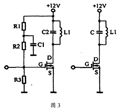
At first, triodes were used to construct the successful amplifier circuit, but the temperature performance was not stable enough, and then field effect tubes were used. The field effect transistor belongs to the voltage control element, which is a triode similar to the electron tube. Compared with the bipolar transistor, the field effect transistor has high input impedance, low input power consumption, good temperature stability, good signal amplification stability, and signal The distortion is small, the noise is low, and its amplification characteristics are better than that of the electronic triode. The three resistors R1, R2, and R3 in the power field effect tube circuit in Figure 3 are connected in parallel to the gate G of the field effect tube. The high frequency oscillation of the front stage The circuit is also connected to G; the primary S is directly grounded; the drain D is connected to the LC oscillator circuit, and its resonant frequency is the same as the high-frequency oscillation frequency of the previous stage. The circuit is shown in Figure 3.

2.4 Transmitting and receiving coil circuit design
Both the transmitting and receiving coils are wound with 12 turns of enameled wire with a diameter of about 0.5 ram, and the diameter of the coil is about 80 r. The function of the transmitting module is to efficiently convert the DC energy into a radio frequency power signal so that the receiving circuit can make full use of the energy. The receiving module is a module that processes the energy after receiving the energy of the previous stage. In order to meet the needs of practical applications, it is necessary to rectify, filter, step down and stabilize the received RF signal, and the processed DC voltage can be used by other loads. The module mainly includes a rectifier circuit and a step-down circuit.
2.5 The overall schematic diagram of mobile phone wireless charger
A wireless charging circuit composed of a CD4069 crystal oscillator circuit and a power FET. The limit voltage of the CD400 series CMOS circuit of the charging circuit is 18v, and the no-load voltage of the unstable AC 12v voltage after rectification and filtering may exceed 18v, so the power supply voltage of CD4069 is provided by the three-terminal voltage regulator integrated circuit 7805. All unused input terminals of the CMOS circuit are connected to appropriate logic levels, and the crystal oscillator is connected to a single-gate oscillator. The oscillation output is sent to the grid G of the power field effect transistor after secondary buffering. The bias voltage and leakage circuit are set on the pole circuit to ensure the stable operation of the circuit.
Summary and Outlook
This product has been completed and can wirelessly charge mobile phones. The wireless distance is 3cm. If a larger distance is required, the number of coil turns and the number of power amplifier circuits need to be increased to generate a stronger alternating magnetic field around the transmitting coil for the receiving coil. Receive at a greater distance. The receiving coil can be embedded in the mobile phone, and the coil can receive signals through the back cover (tested successfully). If this product can be produced and launched, it is believed that various mobile phones will be embedded with receiving coils during production to cater to mobile phone wireless chargers, and it will be more convenient to use. Some mobile phone manufacturers will even buy out the property rights of wireless chargers and use wireless charging as a mobile phone. unique selling point.
The above is the example of wireless charger technology and circuit board development introduced by Shenzhen Zuchuang Microelectronics Co., Ltd. for you. If you have wireless charger solution development needs, you can trust us. We represent a variety of single-chip microcomputers, voice chips, dual-mode Bluetooth ICs, and wifi chips. Brands include Songhan MCU, Yingguang MCU, Jerry Bluetooth, Ankai Bluetooth, Allwinner, and Realtek. Our technical services include: PCB design, microcontroller development, Bluetooth solutions, software and hardware custom development, APP development, small program development, WeChat official account development, etc. It can also undertake the design of intelligent electronic products, the development of living appliances, the research and development of beauty equipment, the application of Internet of things platform, the smart home control system, the development of TWS earphones, Bluetooth earphone speakers, the development of children's educational toys, the design of electronic education products, etc.
Proposal recommendation
- TOP


