- Home >> News >> Blog articles >> Appliances & Tools
Design and development of disinfection cabinet control circuit board
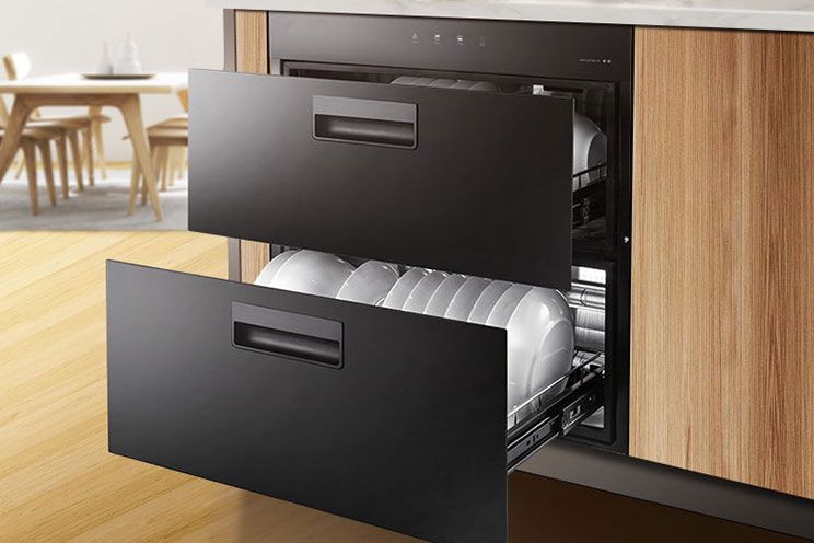
In the past, the disinfection cabinet was controlled by PIC16C5 single-chip microcomputer, and the system resources of AT89S52 single-chip microcomputer are more abundant: built-in RAM32kB module, built-in 8-digit dynamic digital display module, built-in 8×8 dot matrix display module, 4-digit static digital display module, built-in 4-way dial Automatic switch, built-in 8-bit LED light-emitting diode, built-in 3-way adjustable voltage between 0-5V, built-in 2-way SPI and I2C bus interface. The MCU not only provides rich hardware resources, but also provides good host computer control software, which can be realized through the functional operation of the software: debugging and compiling of source code, finding and correcting errors, online code download and other functions. Based on the above advantages, this paper adopts AT89S52 single-chip microcomputer to realize the control system of disinfection, heating and lighting of the disinfection cabinet.
1. Composition and block diagram of disinfection cabinet system
The control system of AT89S52 single-chip microcomputer is adopted in the disinfection cabinet, and its hardware is composed of seven modules including main control circuit, key circuit, relay control circuit, working indicator light, buzzer, digital tube display circuit and power supply circuit. The software part adopts the more popular and more practical C language programming, which realizes setting different disinfection and drying programs through buttons, using timers to implement scanning timing in different links, using program judgment to start the work of corresponding relays, and controlling light-emitting diodes to indicate different jobs State and other functions, and finally combine the software program with the hardware circuit to realize the control of the hardware by the software.
Figure 1 is a block diagram of the system design, in the figure: LED1, LED2 are ozone disinfection indicator lights; LED3, LED4 are heating indicator lights, and all the indicator lights are off when starting up. The key KEY1 is a demonstration key, which is used to artificially reduce the disinfection and heating time set in the software. The button KEY2 is the setting button, press KEY2, LED1 lights up, the ozone relay is turned on, and starts to work; 45 minutes later, LED1 goes out, LED2 lights up; 45 minutes later, LED2 turns off, LED3 lights up, and at the same time the ozone relay is released, and the heating relay sucks in Together, the ozone disinfection is over and enters the heating and drying stage. After 30 minutes, LED3 goes out and LED4 lights up, and after another 30 minutes, LED4 goes out, the heating relay is released, and the whole process of disinfection and thermal drying ends. When different types of disinfection and heating and drying are required, you can press the key KEY2 to select. Each time you press KEY2, the lit LED indicator will move down by 1, and only the rest of the disinfection and drying procedures will be carried out. The button KEY3 is a lighting button, which is used to control the lighting in the disinfection cabinet.
2. Hardware design of disinfection cabinet system
The main control circuit is realized through the programming of the single-chip microcomputer AT89S52: set different disinfection and drying programs through the buttons; use the timer to implement the scanning timing of different links; use the program judgment to control the work of the corresponding relay; control the light-emitting diodes to indicate different working states, etc. Function. The demonstration key KEY1 is connected to the P3.6 port, the setting key KEY2 is connected to the P3.7 port, and the lighting key KEY3 is connected to the P3.5 port. Through software programming, different keys represent different working states. P3.1~P3.4 are respectively used as the output port of LED1~LED4 indicator diodes to indicate different working status modes of the disinfection cabinet: when LED1 is on, it indicates that the disinfection cabinet is working in the mode of disinfection for 45min2disinfection for 45min2heating for 30min2heating for 30min; When LED2 is on, it means that it is working in the mode of disinfection for 45min2heating for 30min2 and heating for 30min; when LED3 is on, it means it is working in the mode of heating for 30min2; And P1.2~P1.4 ports are respectively used as the control output ports of heating, lighting and ozone relays. The digital tube display adopts a 3-digit LED seven-segment digital display, and the P0.6~P0.4 ports are respectively used as the bit selection ports of the digital tube display, and the P2.0~P2.7 ports are used as the font code output ports, and dynamic scanning is adopted. The display mode lights up the respective digital tubes in turn. Use the P1.1 port to control the work of the buzzer. When the keys KEY1, KEY2, and KEY3 work, the buzzer starts to work. Set the time for the buzzer to sound in the software. When the time is up, the buzzer stops working . The power supply circuit adopts a linear voltage regulator circuit, and the LM7805 three-terminal voltage regulator block outputs a stable voltage of 5V to supply power to the circuit.

3. Software design of disinfection cabinet system
The software of the system is written in C language, adopts the modular design idea, divides the design into corresponding program modules, designs and debugs them separately, and enhances the orderliness of the program. At the same time, it also adopts top-down program design form, external devices use interrupt mode to communicate with CPU as much as possible, software anti-interference design and other characteristics, so as to facilitate system modularization, improve program efficiency and system reliability.
3.1 The main program design of the system
It is mainly to realize the link of each module program. The main program first performs the power-on initialization, including the initialization of the status indicator light, the initialization of the digital tube position selection signal, and the initialization of the relay control signal, all of which are initialized to the off state. After the initialization is completed, the single-chip microcomputer continues to circulate, and performs corresponding key scanning, key processing, status display, and relay work according to different inputs.
3.2 Programming of key scanning and processing
Key scanning is the premise preparation for key processing. First, check whether there is a key pressed. If there is a key pressed, first go through a 10ms delay to debounce to prevent interference and misoperation. Then re-scan, if the two scans before and after are the same, then set the key press flag, and send the corresponding key value to the key processing program.
3.3 Nixie tube display and relay control program design
The status display adopts the dynamic scanning display method to light up the respective digital tubes in turn. The work of the relay depends on the mode of the disinfection cabinet and the set minutes. When it is in state 1, the ozone relay starts to work, and then starts the countdown for 45 minutes of disinfection. When the number of minutes is reduced to 0, Just enter the next state (that is, state 2), the ozone relay continues to work for 45 minutes, and after 45 minutes of ozone disinfection, it enters state 3, the heating relay starts to work, and the countdown to 30 minutes of heating begins. When the number of minutes is reduced to 0, it will Enter state 4, the heating relay continues to work for 30 minutes, after 30 minutes of heating, enter state 0 and wait again.
Summarize
This paper follows the principle of reliable hardware circuit and easy operation, and fully utilizes the rich resources of the AT89S52 single-chip microcomputer system. Through the complete design of hardware and powerful programming of software, the function control of the disinfection cabinet is realized, which has practical application value.
The above is an example of the design and development of the disinfection cabinet control system introduced by Shenzhen Zuchuang Microelectronics Co., Ltd. for you. If you have the development needs of disinfection cabinet control circuit, you can trust us. We represent a variety of single-chip microcomputers, voice chips, dual-mode Bluetooth ICs, and wifi chips. Brands include Songhan MCU, Yingguang MCU, Jerry Bluetooth, Ankai Bluetooth, Allwinner, and Realtek. Our technical services include: PCB design, MCU development, Bluetooth solution, software and hardware custom development, APP development, small program development, WeChat official account development, etc. It can also undertake the design of intelligent electronic products, the development of living appliances, the research and development of beauty equipment, the application of Internet of things platform, the smart home control system, the development of TWS earphones, Bluetooth earphone speakers, the development of children's educational toys, the design of electronic education products, etc.
Proposal recommendation
- TOP


