- Home >> News >> Blog articles >> Appliances & Tools
Design and development of electric pressure cooker control panel
From the perspective of the structure of the electric pressure cooker, its development starts from the general simple electric heating pressure cooker, only changing the heating method, its control is not perfect, and it is difficult to realize automatic control. Considerable changes have been made on the basis, and the separation structure of the pot cover of the compression type seal and the floating type seal has occurred. In terms of functional operation and technical application, in addition to traditional mechanical control, a lot of electronic control methods have been added, which greatly improves the safety, functionality and automatic control capabilities of electric pressure cookers.
1. The structure of the electric pressure cooker
In addition to some basic devices shown in Figure 3-1, electric pressure cookers include sealing devices, exhaust devices, control circuits, locking devices, inner tanks, temperature control devices, electric heating devices, timing devices, etc., and some systems also include some safety devices. Devices, such as: cover opening safety device, pressure relief device, cover closing safety device and other protection devices realized by software, etc. Among them, the function of the opening safety device is that when there is a certain pressure in the pressure cooker, no matter what the reason, the cover will It cannot be opened to avoid the pressure inside the pot from hurting people; the safety device for closing the lid is that when the lid and the body of the pot have not been fully engaged, the heater should be in a disconnected state to avoid the pressure rising and causing the pot to burst; the pressure-limiting exhaust valve is the cooking process In order to keep the pressure in the pot within a certain pressure range, the software controls the switch of the exhaust valve to control the pressure to achieve the best cooking effect; the pressure relief device can be manually released when the pressure limiting exhaust valve fails. pressure to ensure safety.
2. Working process and function design of electric pressure cooker
The working process of the electric pressure cooker is as follows: the user puts in the food, closes the lid (the lid switch detects that it has been closed), powers on, the buzzer beeps for a long time, the LED displays all 8, and the electric pressure cooker enters the standby state, and there is no display in this state , no alarm, that is, no action is taken; if you select the function key, select the pressure holding time, the appointment time (optional), and press the start key, the electric pressure cooker starts to work: the LED seven-segment display shows the working status; the upper and lower temperature The temperature is detected by the sensor, and the data is sent to the CPU for analysis and calculation. The fuzzy neural network is used as the controller. According to the proportional relationship between temperature and pressure, the pressure value in the pot is measured by the reed switch; it is controlled according to the cooking process curve of relevant experts. Temperature and pressure, the way to control the temperature is to control the on-off of the relay by outputting the PWM waveform of the microcontroller, so as to control the heating power; the way to control the pressure is to control the on-off of the solenoid valve to control the switch of the exhaust valve. At the end of the control, it is necessary to ensure that the air pressure in the pot is within the safe air pressure range before opening the cover, otherwise the mechanical and electrical interlock will prevent the cover from being opened. At this time, emergency hand exhaust or manual exhaust is required until the air pressure is lower than 0.05 atmospheres. open the lid. In addition, various safety accident prevention measures are essential.
The functions realized in the whole process are described as follows:
(1) Timing/reservation function: users can choose the pressure holding time according to their personal taste and preferences. If the personal favorite food is soft, the pressure holding time should be increased to achieve timing. The maximum timing time is 120 minutes; users can choose according to their daily practice Make an appointment to start up and perform intelligent actions. For example, make an appointment to start up at 5:00 pm before leaving the house at 8:00 in the morning, and the electric pressure cooker will automatically start up and work at the scheduled time, realizing the appointment function.
(2) Function selection: The optional functions include cooking rice, porridge, soup, beef and mutton, tendons, chicken and duck meat, fish, chicken wings, steamed eggs, cakes, pancakes, etc., realizing multiple functions in one pot.
(3) Intelligent control: The designer controls the cooking process according to the expert cooking curve and combined with intelligent control technology. The user only needs to select the type of food, and the follow-up work is completely controlled by the single-chip microcomputer, and the user realizes one-key control.
(4) Fault detection: Fault detection includes sensor open circuit, short circuit detection, no pot detection, undervoltage, overvoltage detection (referring to voltage), overcurrent detection, over temperature detection, overpressure detection (referring to pressure) and other accidental fault detection wait.
(5) Alarm and reminder function: When the electric pressure cooker is turned on, the CPU detects and judges that there is an abnormal situation, or when the electric pressure cooker completes the task according to the user's settings, the buzzer and display will give an alarm or prompt as needed.
(6) Protection function: After starting up, when the CPU detects a fault, it should take action to avoid damage to the device; the designer adds an anti-dry function to the control system according to the problems encountered by the user in daily use, such as dry burning, etc. , considering the hazards brought by steam pressure, multiple protections are added, such as automatic heating time control system, abnormal pressure removal system, automatic pressure relief system, pressure knob tightening device, these systems keep the knob automatically locked after cooking starts If the lid is not locked or there is an abnormal situation, the system will automatically release the pressure to ensure the safety of the pressure cooker.
(7) Shutdown processing: Shutdown signals mainly come from the keyboard, fault and alarm detection, timed out, other external interruptions, and entering the heat preservation state after the cooking process is completed, etc. When a shutdown signal is detected, all controls are turned off.
3. Control system function realization hardware design
The block diagram of the hardware design structure of the electric pressure cooker control system is shown in Figure 3-2. The hardware system is mainly divided into a power board and a control board. The input and output of signals are mainly controlled by the single-chip microcomputer, and the collected information is analyzed and calculated according to the relevant rules to give the control strategy. Below we introduce the main functional structure sub-modules.
3.1 Microcontroller and its peripheral circuits
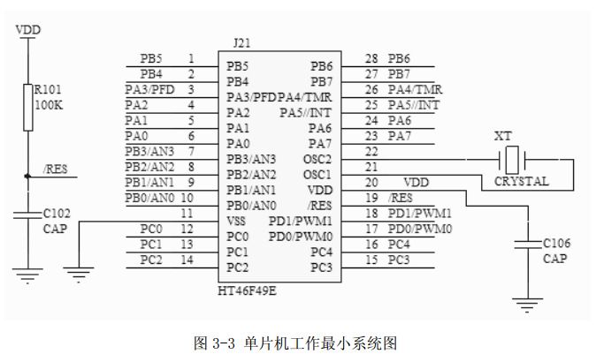
(1) CPU: CPU is the hardware core of the control system. The selection of single-chip microcomputer is particularly important. Based on the principle of suitable function, stability, reliability and economical benefits, we choose the Holtek series single-chip microcomputer which has a certain status in the application of household appliances. The intelligent electric pressure cooker has high requirements on temperature control, and the hardware requires high detection accuracy, which puts forward certain requirements for the A/D conversion accuracy of the single-chip microcomputer. We choose the economical A/D conversion HT46F49 single-chip microcomputer, as shown in Figure 3- 3 is the minimum system diagram of the single chip microcomputer. The microcontroller includes an integrated 4-channel 9-bit A/D converter, two-channel 8-bit pulse width modulation output, and 23 I/O ports. At the same time, it contains extremely strong internal features, such as built-in crystal and RC oscillator drive circuit (can be selected according to needs), PFD function, pause, wake-up function, watchdog timer, low voltage monitoring automatic reset, programmable frequency divider Etc. This low-power consumption and high-performance feature enhances the flexibility of the single-chip microcomputer, and only needs to add fewer external devices in practical applications, which reduces the cost of the entire product.

(2) A/D conversion: The quality of A/D conversion plays a vital role in the electric pressure cooker detection system. The structural block diagram of the detection system is shown in Figure 3-4.
In Figure 3-4, the sensor performs A/D conversion on the collected information, and the single-chip microcomputer analyzes and processes the conversion result, and then transmits it to the actuator. It can be seen that the A/D conversion result directly affects the accuracy of the detection quantity. The HT46F49 chip has 4 A/D converter inputs, and all analog inputs are shared with the I/O pins of the PB port. If these pins are used as A/D inputs instead of general I/O pins, the corresponding bits in the A/D conversion control register ADCR must be set correctly. The A/D function is not included in the mask option. If these pins are used as I/O pins, you can still choose whether to connect a pull-up resistor through the mask option. However, if they are used as A/D inputs, these pins The pull-up resistors on will be disabled automatically.
(3) PWM: The PWM register is 8 bits, indicating the duty cycle of each modulation cycle in the output waveform. By setting a specific value for the corresponding PWM register, the PWM function can provide a waveform with an adjustable duty cycle and a fixed frequency. In order to increase the PWM modulation frequency, each modulation period is modulated by two or four independent modulation subsections. When using PWM, as long as the required value is written into the corresponding PWM register, the internal hardware of the microcontroller will automatically subdivide the waveform into sub-modulation periods. The method of dividing the original modulation period into 2 or 4 sub-periods makes it possible to generate higher PWM frequencies. As long as the generated PWM pulse period is smaller than the time constant of the load, the PWM output is more suitable, because the long-time constant load will Will average the pulses of the PWM output.
3.2 Power distribution, heating plate power drive circuit
In Figure 3-7, before entering the safety capacitor CO and varistor RZ, a fuse is connected in series to prevent the circuit from being burned out due to excessive current. The U and Q points are stabilized at +15V due to the addition of a voltage regulator tube, which supplies the relay power supply, and the CD7805 inputs +5V The voltage is supplied to the microcontroller power supply.
There are two main ways to drive the power of the heating plate, which are relay control and thyristor control. The advantage of using thyristor drive is fast and smooth response, suitable for high frequency systems. The disadvantage is that detection and connection are inconvenient, unsafe and complex circuits. , although it has no effect on the system work, it is very easy to cause danger when it is repaired or disassembled by the user without permission. In order to ensure safety and consider the design convenience and cost, we choose the relay drive mode. Although it adopts switch control, the temperature is smooth Relatively not as good as thyristor phase shift control, but safe. The driving circuit of the relay is composed of transistors, resistors and relays. PD1/PWM1 outputs PWM waveforms to control the opening and closing of the relay through the triode.
3.3 Solenoid valve control circuit
The solenoid valve is at the top of the pot, and the model used is a D-frame push-pull solenoid. Working principle: When energized, the electromagnetic coil generates electromagnetic force to lift the closing member from the valve seat and push the valve; when the power is off, the electromagnetic force disappears, the spring presses the closing member on the valve seat, and the valve returns to its original position. This principle is applied to the design. When the solenoid valve is energized, the contact in front of the valve pushes the exhaust valve outward, the valve opens, and the gas in the pot is discharged outward. When the power is lost, the valve contact returns to the original state, and the exhaust valve Closed, the gas in the pot cannot be discharged outside, and the solenoid valve is used to control the switch of the exhaust valve. The control circuit diagram is shown in 3-8, and the solenoid valve is controlled by the on-off of two triodes. The specific software setting only needs to set the pa5 port as the output, _pa5c=0; _pa5=1; the power valve is opened, after a period of delay, set _pa5=0, and the power-off valve is closed.
3.4 Temperature detection circuit design
For temperature measurement technology, generally divided into two types: contact temperature measurement and non-contact temperature measurement. Due to the particularity of the temperature measuring object, this system adopts non-contact temperature measurement. The advantage is that it has no effect on the temperature measurement field and can measure the temperature of the area. The disadvantage is that there are large errors in the measurement and the structure is complicated, which needs to be reduced after many tests. error. NTC is the abbreviation of negative temperature coefficient thermistor. It is a heat-sensitive semiconductor ceramic element made of transition metal oxide as the main raw material and made of electronic ceramic technology. The resistance value of this element decreases with the increase of temperature. Using this characteristic can be made into temperature measurement, temperature compensation and temperature control components.
Summarize
This paper analyzes the structure and working principle of the electric pressure cooker, transforms the original electric pressure cooker, designs a safe and practical function mode, introduces the characteristics of the CPU and the related hardware circuit design, including the power module, temperature detection module, voltage detection Modules, solenoid valves, relay drive modules, power-down storage, key display alarm modules, etc.
The above is the development example of the electric pressure cooker introduced by Shenzhen Zuchuang Microelectronics Co., Ltd. for you. If you have the development needs of smart electric pressure cooker solutions, you can trust us. We represent a variety of single-chip microcomputers, voice chips, dual-mode Bluetooth ICs, and wifi chips. Brands include Songhan MCU, Yingguang MCU, Jerry Bluetooth, Ankai Bluetooth, Allwinner, and Realtek. Our technical services include: PCB design, MCU development, Bluetooth solution, software and hardware custom development, APP development, small program development, WeChat official account development, etc. It can also undertake the design of intelligent electronic products, the development of living appliances, the research and development of beauty equipment, the application of Internet of things platform, the smart home control system, the development of TWS earphones, Bluetooth earphone speakers, the development of children's educational toys, the design of electronic education products, etc.
Proposal recommendation
- TOP


