- Home >> News >> Blog articles >> Appliances & Tools
Intelligent remote control fan control board development
With the rapid development of society, fans, as an ordinary household appliance, should improve the technology of fans in addition to their advantages of cheap price, small size, light weight, and easy to move, so as to increase their market competition. force. Most of the common fans use manual operation speed regulation or control switch, which cannot detect the indoor temperature, and only complete the control of the fan according to the actual operation of people, often when the room is empty. If the fan is still turned on, this not only wastes resources, but also reduces the service life of the fan. If the fan can run or stop in a timely manner according to the presence or absence of people, and can detect the indoor temperature. Adjusting the speed of the fan according to the artificially set temperature will make the fan closer and facilitate our life. Apply these situations to the control system of the fan. In order to realize the intelligentization of the fan.
1. Overall scheme design of smart fan
Aiming at the defects of the current fan control system, the design idea of the smart fan is proposed. Realize the refinement and humanization of fan speed control. When the room temperature reaches or exceeds the artificially set temperature and someone is detected, the fan will automatically turn on and change the wind speed according to the change of room temperature; and when the room temperature is lower than When the temperature is artificially set or when no one is present, the fan will automatically turn off.
Through the analysis of the control system of the fan, the overall design method of the smart fan is proposed. This design mainly realizes the functions of the following parts:
1) Wind speed control function: According to the set temperature, the motor speed can be controlled, and the wind speed of the fan can be adjusted to achieve a better cooling effect. 2) Remote control function: through the mobile phone Android client and Bluetooth technology to remotely control the fan's speed regulation and operation status such as running and stopping. 3) Real-time temperature display function: the real-time monitoring of the current ambient temperature is realized through the sensor, and the current indoor temperature and the set temperature are displayed through the display terminal, so that users can refer to the indoor temperature to set the temperature when the fan is turned on.
The overall design block diagram of the system is shown in Figure 1. The hardware part is composed of 8-bit single-chip microcomputer, infrared temperature sensor and Bluetooth device. Detect the existence of people through the infrared temperature sensor, and transmit the information of people to the 8-bit microcontroller to control the start or stop of the fan. At the same time, when the fan starts, it detects the current temperature in the room and displays it on the display screen; connects the Android client through the Bluetooth module , transmit corresponding information to control the fan, and realize the remote control of the fan.
2. Hardware circuit design of remote control fan
2.1 MCU control module
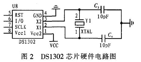
The intelligent remote control fan uses an 8-bit microcontroller as the core controller to control and coordinate the normal operation of the entire system. In the design, the DS1302 clock real-time module is used to realize the real-time display and timing function of the temperature. The DS1302 provides accurate time information to the 8-bit single-chip microcomputer, and the single-chip microcomputer controls the timing program to complete the timing system of the remote control intelligent fan. DS1302 chip external circuit connection diagram is shown in Figure 2.
A crystal oscillator circuit is connected externally through the X2 and X1 pins of DS1302 to generate a reference clock signal, and obtain an accurate second signal through frequency division, while improving stability and efficiency to achieve a timing function.

2.2 Temperature detection feedback and display module
Choose DS18B20 temperature sensor to realize real-time temperature detection. By being shielded or detecting the reflected light beam, the photoelectric sensor cyclically scans and collects infrared information of the human body. When the photoelectric sensor detects the existence of a person and reaches the artificially set temperature, it transmits the external information to the 8-bit single-chip microcomputer, so that the 8-bit single-chip microcomputer Controls the command to turn on the fan. When no human presence is detected and this state lasts for a long time, the fan is automatically turned off to save energy.
DS18B20 and DS1302 send the temperature information to the 8-bit chip, and then present the current temperature and the set temperature value through the display module.
DS18B20 realizes the information transmission between it and the one-chip computer through a line DQ of losing people. Connect a 1OKQ resistor in series. Then connect the input terminal with the P13 port of the microcontroller to complete the transmission of temperature information. And the OUT pin of the photoelectric switch is connected with the P32 pin of the single-chip microcomputer. The reset pin RST of LCD5110 is connected with the P14 port of the one-chip computer, and the DIN pin is connected with the P17 port of the one-chip computer as the data input end.
2.3 Motor Control Module
The control of the motor is an important aspect in the whole control system, which realizes the control of the fan speed. The MCU has its own PWM module, and the 8-bit chip obtains temperature information from DS18B20, and outputs different PWMs to the drive module L298N according to different set temperatures. The drive module L298N will have different PWMs corresponding to the speed. The L298N will change the output voltage according to the corresponding PWM, and the input voltage to drive the fan will change. By transmitting it to the fan, the speed of the fan can be controlled to reach the temperature you set. Value, the speed of the fan is almost close to infinitely variable.
The OUT1 and OUT2 of the drive module L298N are respectively used as the data input and output terminals of the fan. The two pins IN+ and IN- are respectively connected to the power supply and the ground wire, and the EN terminal is connected to the P13 port of the single-chip microcomputer. PWM signal to control the speed and stop of the motor.
2.4 Bluetooth technology control module
A Bluetooth module is implanted in the design, and a special Android client is designed for this purpose, so that people can remotely control the fan. To realize the communication between the Bluetooth module and the microcontroller, the Bluetooth module is directly connected to the microcontroller and interacts with the mobile phone client. Connect the TXD terminal in the Bluetooth module to the RXD terminal in the single-chip microcomputer, and connect the RXD terminal in the Bluetooth module to the TXD terminal in the single-chip computer. data, and receive feedback from Bluetooth mobile phones. The bluetooth module is operated by hardware and software at the same time, and can control the operation of the fan through the mobile phone. It can not only realize the timing of the fan's work, but also set the temperature to control the fan's speed.
3. Software program design of intelligent fan
In order to realize the intelligent control requirements of the fan, the main program of the system is realized through functions such as module initialization program, infrared photoelectric display program, bluetooth control program, temperature detection program and LCD display program.
After initializing the data of DS18B20, start to measure the temperature and set the corresponding parameters. The internal temperature processing system calls the corresponding control program for internal judgment, outputs data and displays it through LCD. The one-chip computer STC15F2K61$2 controls DS1302 by calling the corresponding driver program. The program needs to define the address of the DS1302 register and write the control word. And read the data of the DS1302 register. The initialization of DS1302 makes SCLK low. when set high. Data transfer starts. The data on the I/O line is sent to the DS1302 on the rising edge of SCLK.
The host control interface protocol is the interface between the HCI driver of the host and the firmware of the control host located in the Bluetooth communication module, which is included in the Bluetooth protocol stack and used in the hardware part of the Bluetooth communication module. The role of RTS/CTS is to prevent the overflow of the temporary UART buffer.
4. Debugging of intelligent remote control fan system
Manually solder the circuit according to the system circuit schematic diagram. And implant the program into the system. Turn on the power, turn on the fan switch, adjust the operation mode of the fan, make it work in the normal mode, that is, the manual speed control mode of the ordinary fan, and change the rotation speed of the fan by adjusting the gear of the fan. Start the second operating mode, the smart mode, for remote control via Bluetooth technology. Make the fan run in smart mode, the display shows that the current room temperature is 25°C, set the temperature lower than the room temperature, the sensor detects that people are present, and the fan turns on; if the room temperature is lower than the set temperature, the fan stops rotating, which plays a very good role. of temperature control.
The above is the development example of the intelligent remote control fan introduced by Shenzhen Zuchuang Microelectronics Co., Ltd. for you. If you have the solution development needs of smart fans, you can trust us. We represent a variety of single-chip microcomputers, voice chips, dual-mode Bluetooth ICs, and wifi chips. Brands include Songhan MCU, Yingguang MCU, Jerry Bluetooth, Ankai Bluetooth, Allwinner, and Realtek. Our technical services include: PCB design, MCU development, Bluetooth solution, software and hardware custom development, APP development, small program development, WeChat official account development, etc. It can also undertake the design of intelligent electronic products, the development of living appliances, the research and development of beauty equipment, the application of Internet of things platform, the smart home control system, the development of TWS earphones, Bluetooth earphone speakers, the development of children's educational toys, the design of electronic education products, etc.
Proposal recommendation
- TOP


