- Home >> News >> Blog articles >> Appliances & Tools
Development of piece-based electric screwdriver control board
Electric screwdrivers (electric batches, electric screwdrivers) are commonly used production and assembly tools in modern industry, which can improve work efficiency and assembly accuracy. Because the traditional electric screwdriver uses a brushed series motor as the power source, there are shortcomings such as commutation sparks, easy wear, and no intelligent control. Therefore, brushless DC motors (Brushless DC Motors, BLDC for short) using electronic commutation have been developed at home and abroad. A new electric screwdriver as a drive motor. BLDC has high power density, no wear and sparks, simple structure, and convenient maintenance. Equipped with a digital drive controller based on a high-performance microcontroller, it can realize digital stepless speed regulation, and can integrate intelligent functions to enhance the comfort of operation. , increasing the added value of the product.
In the field of precision assembly such as automobile assembly, it is usually necessary to assemble a large number of screws on a workpiece. While assembling, the operator also needs to spend mental effort to count the pieces to ensure that each workpiece is not missing, which increases the workload and is prone to fatigue. As a result, assembly efficiency is affected, and even the product has potential safety hazards. Therefore, designing an intelligent brushless electric screwdriver with functions such as piece counting and alarming is of great significance to the assembly industry.
Based on the brushless electric screwdriver control system, this paper adds an intelligent piece counting function module, and describes in detail the design of the intelligent piece counting module composed of digital tube display circuit, button setting circuit, buzzer prompt circuit and infrared photoelectric switch. And discussed the intelligent piece counting control strategy, and finally made a prototype and verified its operation.
1. The working principle of piece electric screwdriver
The intelligent piece counting type brushless electric screwdriver system consists of starting control panel, forward and reverse control panel, intelligent piece counting module, drive controller, BLDC and deceleration brake mechanism and other components. The drive controller accepts commands such as start, standby, forward rotation, and reverse rotation generated by user operations, and sends control signals to the power drive module to drive the brushless DC motor to run after being analyzed and processed by the corresponding control algorithm. speed output. When mechanical braking occurs when the screwdriver is tightened, the variable speed braking mechanism feeds back a braking signal to the drive controller to control the motor to brake and stop. In addition, the intelligent piece counting module is used to realize the screw assembly and piece counting of the workpiece. It is composed of a digital tube display circuit, a button setting circuit, a buzzer prompt circuit and an infrared photoelectric switch. It has supporting functions such as setting, piece counting and alarm.
2. Hardware circuit design of intelligent electric screwdriver
This paper analyzes the design of the intelligent piece counting module composed of digital tube display, button setting, buzzer prompt and infrared photoelectric switch.
2.1 MCU and peripheral circuit design
In the single-chip microcomputer and the peripheral circuit, the control core is the single-chip microcomputer STM8S103K3 with 8-bit 16 MHz main frequency. The main functions of this microcontroller are:
(1) Integrated EEPROM storage space, with power-off saving function, can be used to save the user's set value for smart piece counting. (2) The integrated buzzer drive peripheral module can directly drive the passive buzzer to emit various notes through the triode. (3) There are 28 I/O port pins, with high current absorption capability, which can directly drive the digital tube, meeting the requirements of the smart piece counting module circuit on the number of pins and driving capability.
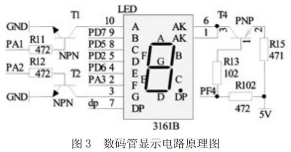
The specific functions of the pins related to the intelligent piece counting module are as follows: (1) Pins PA1, PD7, PD5, PD2, PD6, PA3, PA2, PD3 and PF4 are used to drive digital tubes, and pins PD2 and PD5 are multiplexed as buttons Set the detection pin for the circuit. (2) Pin PD4 is controlled by the buzzer driver peripheral module of the microcontroller, and is used as the signal pin to drive the passive buzzer. (3) In addition to being the SWIM pin of the emulator interface, the pin PD1 is also used as the signal pin of the infrared photoelectric switch. (4) START_IN, DIR_IN and BREAK_IN are the interfaces of start signal, forward and reverse signal and brake signal respectively.
2.2 Digital tube display circuit design
Figure 3 shows the schematic diagram of the digital tube display circuit, based on the common anode 7-segment digital tube 3162B. The pin AK is connected to the 5V power supply through the PNP transistor T4 and the series resistor R15. When PF4 is at low level, the collector-emitter of T4 is turned on, so that the pin AK is pulled up to 5 V potential through the resistor R 15. At this time, it is only necessary to control A, B, C, D, E, F, G The high and low levels of the DP pin can control the corresponding pipe segment to light up or extinguish, forming the corresponding character display. When PF4 is at high level, the AK pin has no voltage, and all tube segments of the digital tube cannot light up. The single-chip microcomputer pins PA1 and PA2 corresponding to the digital tube pins A and G do not have high current-absorbing capability, and must amplify their drive capability through the NPN transistor.

2.3 Button setting circuit and buzzer prompt circuit design
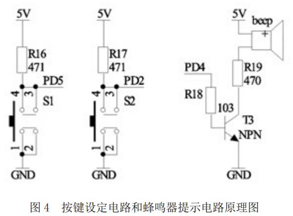
Restricted by the number of I/O pins of STM8S103K3, the detection pins of keys S1 and S2 are shared with the pins PD2 and PD5 of the single-chip microcomputer with pins C and D of digital tubes. As shown in Figure 4, the PD2 and PD5 pins must be configured as an open-drain output mode with an external pull-up resistor during program design, which can avoid the pins from using push-pull high-level output and pressing the button at the same time. Short circuit hazard.
Based on the buzzer driver peripheral module integrated by the single-chip microcomputer, the pin PD4 is connected to the base of the triode T3, and the buzzer is driven by the power amplification of the triode, and the note of "do-re-mi-fat-la-hee-du" can be issued. After specific analysis and design, it is used as a prompt or alarm for the intelligent piece counting function.

2.4 Application design of infrared photoelectric switch
Infrared photoelectric switch is a photoelectric sensor that integrates emission and reception. It has a long detection distance, little interference from visible light, low price, easy assembly, and convenient use. The detection distance can be adjusted according to requirements. Install it on the assembly table. When the workpiece is not placed in the assembly table, the emitted infrared light cannot be reflected to the receiver, and the microcontroller receives the low-level signal output by pin PD1; when the workpiece is placed in the assembly table, the emitted infrared light The infrared light is reflected back to the receiver through the workpiece, and the microcontroller receives the high-level signal output by the pin PD1.
The nixie tube display circuit, button setting circuit and buzzer prompt circuit are all integrated on the intelligent piece counting module board, and the infrared photoelectric switch is connected with the drive controller board through the interface. The intelligent piece counting module board is superimposed on the drive controller board.
3. Design of control strategy for piece-based electric batch
Based on the brushless electric screwdriver drive control strategy, an intelligent piece counting control strategy is added. Intelligent piece counting control strategy is mainly composed of digital tube display method, buzzer prompt method, button operation method and piece counting method.
3.1 Design of digital tube display method
The digital tube is mainly used to display the number of pieces counted and fault display. Design the corresponding program so that it can display "0"~"9" and "E" and "F" characters. In order to make this digital tube display more values, define the decimal point corresponding to the DP on the digital tube to represent the count value The tens digit value is "1", so that the single nixie tube can count the range of 0~19, which meets the piece counting requirements of most workpieces. When the system has a recoverable failure such as undervoltage, the digital tube will display "F" to prompt the user. When serious unrecoverable errors such as overvoltage and overcurrent occur in the system, the digital tube will display "E" to prompt the user.
3.2 Design of starting method for piece counting function
Smart piece-counting type brushless electric screwdriver can work in basic working mode or piece-counting working mode. Within 10 s after the screwdriver is powered on, if the infrared photoelectric switch does not detect that there is a workpiece put into the assembly table, and the single-chip microcomputer only receives a low-level signal, the screwdriver will work in the basic working mode and the piece counting function will not be enabled; If a workpiece is detected within 10 s after power-on, and the single-chip microcomputer detects the process of jumping from low level to high level, the infrared photoelectric switch is considered to be working normally, and the piece counting mode is enabled.
3.3 Key operation method design
After the piece counting mode is enabled, the single chip microcomputer will call out the piece count setting value set last time from its own EEPROM storage space, and display it on the digital tube. If you need to adjust the set value of piece counting, you can press and hold the buttons S1 and S2 at the same time. After 4 s, you will enter the setting state. By operating the buttons S1 or S2, the set value of piece counting can be added or subtracted. After the setting is completed, the buttons S1 and S2 must be pressed again at the same time. After 4 s, the new setting value is confirmed and stored back to the corresponding storage space of the EEPROM.
3.4 Design of piece counting method
When the infrared photoelectric switch detects that the workpiece has been put into the assembly table, the piece counting function is started. Whenever the user operates the control panel to start the electric screwdriver, the single-chip microcomputer adds 1 to the piece count value. When the piece count reaches the set value, the assembly of a workpiece is completed. At this time, the workpiece can be taken out of the assembly platform and replaced with a new workpiece to be assembled, and the piece count value is reset to 0. If the piece counting does not reach the set value, the workpiece will be taken out of the assembly table, and the piece counting value will not be cleared to 0. After the unassembled workpiece is placed again, the assembly piece counting will continue.
3.5 Buzzer prompt method design
The prompt tone of the buzzer is designed as three notes of "Duo", "Duo Reimi" and "Duo Reimi Fashou La Xidu (hereinafter referred to as Duo-du)". Table 1 lists all the situations that need to be pronounced and the corresponding Prompt note, depending on the occasion, the frequency of its pronunciation is also different.
4. Operation verification of intelligent electric screwdriver
First, power on the brushless electric screwdriver, put the workpiece into the assembly table within 10 seconds, or cover the infrared photoelectric switch with your hand. After the single-chip microcomputer detects the level change of the infrared photoelectric switch signal, it will start the smart piece counting function and With the "duo-du" sound of the buzzer.
Next, set the set value of piece counting according to the number of screws to be processed on the workpiece. Press the buttons S1 and S2 at the same time, after 4 seconds, with a sound of "Duo Re Mi", the digital tube displays the initial set value and flashes; operate S1 or S2 to adjust the piece counting set value to 19, then press the buttons S1 and S2, with a sound of "duo-du", completes the saving and exits the setting state.
Put the workpiece into the assembly table, the infrared photoelectric switch outputs a high-level signal, the display value of the digital tube is cleared to 0, and a sound of "duo-du" indicates that the assembly process of the workpiece has started. Every time the electric screwdriver is operated, the number of the digital tube will increase by 1, and when the operation ends, it will be accompanied by a sound of "Duo Lai Mi". When the number of pieces counted reaches 19, it will be accompanied by a prompt note of "Duo-doo", indicating that the assembly of the workpiece is completed. The user takes out the assembled workpiece from the assembly table, and the buzzer is accompanied by a "duo-doo" note. Put the new workpiece to be assembled on the assembly table. After the infrared photoelectric switch detects it, there will be a "duo-du" note, and the display value of the digital tube will be cleared to 0, and a new count can be started.
If the number of counted pieces reaches 16, the user will take the unfinished workpiece out of the assembly table, and the buzzer will give a continuous beeping sound until the workpiece is put back on the assembly table, the alarm sound stops, and the user can continue to complete the work. The remaining 3 times of screw assembly effectively ensure that the workpiece assembly is complete.
Summarize
Based on the developed electric screwdriver control system driven by brushless DC motor, this paper integrates the intelligent piece counting module composed of digital tube display circuit, button setting circuit, buzzer prompt circuit and infrared photoelectric switch, etc., and discusses the intelligent piece counting module in detail. Control strategy, and finally a prototype was produced and verified for operation. The results show that the hardware design of the intelligent piece-counting type brushless electric screwdriver control system is reasonable and reliable, the control strategy is clear and effective, and the user's operation is comfortable. It can be applied to workpiece assembly occasions that require intelligent piece counting.
The above is an example of the design and development of the intelligent piece-counting brushless electric screwdriver introduced by Shenzhen Zuchuang Microelectronics Co., Ltd. If you have a solution development demand for an intelligent electric screwdriver, you can rest assured to entrust it to us. We represent a variety of single-chip microcomputers, voice chips, dual-mode Bluetooth ICs, and wifi chips. Brands include Songhan MCU, Yingguang MCU, Jerry Bluetooth, Ankai Bluetooth, Allwinner, and Realtek. Our technical services include: PCB design, MCU development, Bluetooth solution, software and hardware custom development, APP development, small program development, WeChat official account development, etc. It can also undertake the design of intelligent electronic products, the development of living appliances, the research and development of beauty equipment, the application of Internet of things platform, the smart home control system, the development of TWS earphones, Bluetooth earphone speakers, the development of children's educational toys, the design of electronic education products, etc.
Proposal recommendation
- TOP


