- Home >> News >> Blog articles >> Internet of things
Infrared bluetooth fingerprint combination lock design
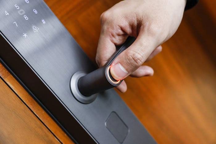
The development of today's intelligent electronic combination lock has reached a very high level. Due to the unprecedented development of electronic components, especially the application of single-chip microcomputers in recent years, both functionality and stability are relatively comprehensive. It was developed earlier in foreign countries, so it is widely used, mainly in places where household decoration is more expensive, such as banks, safes, etc. It is also developed rapidly in China, whether it is self-developed or introduced, it is common in important places. There are also many, because the price is more expensive than ordinary tumbler locks, it was less used in the early years, and now it is becoming more and more common, and the future development will be more and more adopted by the public, because its function and safety are the tumbler locks. Incomparable. The rapid development of fingerprint identification products has benefited from the introduction of low-cost imaging equipment and its rapid development, as well as the research and development of reliable comparison algorithms. On the other hand, fingerprint identification technology, like many other technologies, is also from dedicated to Public utility has gradually become one of the cutting-edge high-tech that people pay attention to, and now it has become a symbol of various high-tech products.
1. Design of Bluetooth fingerprint combination lock based on MCU
In today's Internet era, each of us has a large number of authentication passwords, such as power-on passwords, email passwords, bank passwords, forum login passwords, and so on. Passwords are easy to be forgotten and may be stolen. They can no longer meet the needs in terms of intelligence and security performance. Now various keys, such as door lock keys, car keys, safe keys, etc., also exist like passwords. Obvious loopholes, with the development of society, its security is becoming more and more vulnerable. But we can't avoid this embarrassing problem. We need to confirm personal identity and authority at any time in our life, especially in the information society, people have higher and higher requirements for security, and they also hope that the authentication method is simple fast. In order to solve this long-standing problem, people have turned their attention to the biometric technology that has emerged in recent years, hoping to use the physiological characteristics or behavioral actions of the human body for identification.
Fingerprints refer to the uneven lines on the skin on the front of the fingertips. Although fingerprints are only a small part of human skin, they contain a lot of information. These lines are different in patterns, breakpoints and intersections. They are called "features", medical and permanent, so we can match a person with his fingerprints, and verify his true identity by comparing his fingerprint features with pre-saved fingerprint features.
2. Bluetooth fingerprint password lock function
(1) Key input uses a 4×4 keyboard to input passwords and select and switch between various modes to realize human-computer interaction.
(2) The display part adopts LCD12864 liquid crystal screen to display the status of the current password lock.
(3) The processor uses STC12C5A60S2 high-speed 1T single-chip microcomputer as the main control chip to realize data collection and processing.
(4) The temperature sensor uses a DS18B20 high-precision temperature sensor to monitor the current ambient temperature.
(5) The buzzer uses an active buzzer to realize prompting and alarming.
(6) The Bluetooth module uses HC-05 to realize wireless communication with the mobile phone, and realizes the unlocking function through the mobile app.
(7) The memory chip adopts 2 4 C 0 2 electrically erasable and write-protected EEPROM to store relevant data.
(8) The fingerprint module uses the FM10 fingerprint recognition module, which has high recognition rate and the false recognition rate is less than 0.001%. It can add, delete and clear fingerprints.

3. Working process of Bluetooth fingerprint combination lock
(1) When the device is powered on, it automatically detects whether the administrator password data in the EEPROM is valid. If the valid system operates normally, if the password data is invalid (for the first time), it is required to set the administrator password.
(2) After entering the main interface, it will display welcome to use the fingerprint Bluetooth access control system, and the current ambient temperature. At this time, press the B key to unlock the manual input unlock password, the C key to cancel (Cancel), and the D key to confirm (Determine). If the password is entered correctly, the buzzer will sound once, and the LCD will prompt that the door has been opened. After 5s, the relay picks up. The system returns to the main page. If the input is wrong, it will prompt that the password is wrong, and you still have (n) chances. If the input is wrong 3 times in a row, the LCD will prompt that the keyboard is locked and requires the use of fingerprints to unlock it.
(3) When the system is on the main page, press the A key to be the administrator key (Administrator), and it is required to enter the administrator password. The administrator password and unlock password are independent of each other. If the administrator password is entered correctly, it will enter the administrator mode. The up and down keys move the cursor arrow, the D key confirms and the C key cancels to switch on password management, fingerprint management, manual unlocking and Bluetooth mode. Password management is divided into modifying the unlock password and the administrator password. When modifying the password, it is required to enter the new password twice. If the two inputs are consistent, it will prompt that the password has been modified successfully. If the two inputs are inconsistent, it will prompt that the password modification has failed. If the two inputs are inconsistent . Fingerprint management includes adding fingerprints, deleting fingerprints, searching fingerprints and clearing the fingerprint database. You can delete a specified single fingerprint. There are LCD prompts for the operation, which is easy to use. Manual unlocking means unlocking directly. The Bluetooth mode prompts the current Bluetooth status, and you can turn off or turn on the Bluetooth status according to the prompts.
(4) When the Bluetooth mode is turned on, you can connect the Bluetooth module in the lock body through the mobile phone APP, and use the mobile phone instead of the keyboard to operate the combination lock.
4. Design of infrared smart password lock based on 51 single-chip microcomputer and wireless communication
With the advancement of science and technology, the use of smart combination locks is increasing. Mechanical or electronic coded locks usually adopt rotary dials or buttons, and each unlocking is carried out by manually rotating the rotary dial or pressing the buttons to input the password. Relying on the turntable to unlock, the lock wears a lot and the service life is low; using the key to input the password to unlock, the input is cumbersome, and there is a problem of being locked after entering the wrong password many times. In view of this, an infrared smart combination lock based on single-chip microcomputer and WiFi communication is designed.
4.1 Composition of infrared smart combination lock
The infrared smart combination lock is composed of three parts: an infrared decoding lockset, a liquid crystal combination key and a mobile phone application software. The infrared decoding lock includes 51 single-chip microcomputers and multiple decoding units, and each decoding unit includes a pair of infrared emitting tubes and receiving tubes; the single-chip microcomputer receives signals from the infrared receiving tubes. The LCD password key includes a single-chip microcomputer and a dot-matrix LCD screen. The single-chip microcomputer controls the display position of the black dot matrix on the LCD screen, that is, the password graphic, the number of graphic groups, and the interval time for each group of graphic switching.
The user downloads the "Smart Combination Lock" App on the mobile phone, registers and logs in with a unique user name and password for each set of locks, and can freely set the password graphics, the number of graphic groups and the switching time of each group of graphics on the setting interface, and click the "Settings" button to change the unlock password.
4.2 Working Principle of Infrared Smart Combination Lock
The single-chip microcomputer at the key end drives the LCD screen to display different graphics of the specified number of groups within the set time; the single-chip microcomputer at the lock end is in a dormant state when it is not working, and it will be awakened once the key is close, and the single-chip microcomputer drives all infrared emission tubes to emit infrared rays. The upper non-black dot matrix is reflected and received by the paired infrared receiving tube. The single-chip microcomputer reads the status of the infrared receiving tube and analyzes the password pattern through software; if the decoded pattern is consistent with the password pattern, the lock will be unlocked. The LCD screen can be set into multiple groups of graphics, and the switching time of each group of graphics can also be set. The lock side decodes the switching time of each group of graphics, the number of graphic groups and the style of each group of graphics must be consistent with the settings on the key side to open the lock. The MCU serial port on the lock end and the key end are both connected to a serial port WiFi module, which is used to receive the number of password graphic groups sent by the mobile app, the graphic switching time and other parameters.
5. Hardware Design of Infrared Smart Combination Lock
This system uses AT89C51 as the core control component. The 51 series single-chip microcomputer adopts VLSI technology to integrate the central processing unit CPU with data processing capability, random access memory RAM, read-only memory ROM, various I/O port interrupt systems, timer/counter and other functions into a silicon chip A small but complete embedded computer system formed on the above is one of the most cost-effective and widely used 8-bit single-chip microcomputers. The lock end and the key end each use a single-chip microcomputer as the control core. The P0 port of the single-chip microcomputer at the lock end controls the triode to be turned on or off, and the triode drives the infrared emitting tube to emit infrared rays; the P1 and P2 ports are respectively connected to 8 infrared receiving tubes, and the status of the infrared receiving tube is read and analyzed. If the decryption is successful, the drive relay is energized, and the lock motor is turned on to unlock. P3.3 is connected to the buzzer to alarm, once the parsed password is inconsistent with that on the lock end, the buzzer will alarm.
The single-chip microcomputer at the end of the LCD password key is connected to the dot-matrix LCD screen, and the LCD screen is controlled by software to display different dot-matrix graphics. This design uses LCD1602 liquid crystal screen, which can display two lines with 16 characters in each line. There are all black "■" characters in the character library, and the software controls the LCD to display each character as all black or blank. There are more than 65,000 types of graphics composed of two lines of characters, that is, each group of graphics is one of more than 65,000 types. Two groups, three groups, or even more groups of password graphics can be set through programming, and the switching time between each group of graphics can also be set. As such, the complexity of the password is extremely high. sw1 is the start button, which wakes up the single-chip microcomputer at the key end, and sw2 is the key-off button, which controls the single-chip microcomputer to enter the sleep state to save battery power.
Both the lock end and the key end are connected with a serial port WiFi module. This design uses the ESP8266 serial port WiFi module, which is a new generation of embedded WiFi module with small size and low power consumption. UART interface is adopted. The serial port WiFi module is based on the general serial interface characteristics, conforms to the IEEE802.11 protocol stack network standard, and has a built-in TCP/IP protocol stack, which can realize any transparent conversion between the user's serial port, Ethernet, and wireless network (WIFI). Make the traditional serial device better join the wireless network, through the serial WiFi module, the traditional serial device can transmit its own data through the Internet network without changing any configuration. The UTXD of the module is connected to the TXD of the single-chip microcomputer, and the URXD is connected to the RXD of the single-chip microcomputer. In this way, the parameters set in the mobile app can be sent to the key and lock side MCU through the WiFi to serial port module, saving the trouble of downloading the program with a dedicated downloader.
6. Software Design of Infrared Smart Combination Lock
The software is written in C language, many library functions can be called, the programming is simple, and the portability is good. The lock and key end programs are written in C language of single chip microcomputer.
The single-chip microcomputer at the lock end is usually in a dormant state, and is awakened when the key is close, and then starts to continuously read the status of the P1 and P2 ports connected to the infrared receiving tube. When the status of P1 and P2 ports are all 0, that is, the infrared receiving tube has not received Signal, indicating that the LCD key has not been attached to the lock. When the P1 and P2 ports are all 1, it indicates that the key has been attached to the lock and enters the stage of reading graphics. Compare the read graphic with the set password graphic, and if they are consistent, read the second graphic at the set time interval; in this way, read the second graphic according to the set graphic style, group number, and the interval time between each group of graphic switching. Get the status of P1 and P2 ports and analyze them. Until each group of graphics analyzed is completely consistent with the set graphics, the P3.2 port of the single-chip microcomputer drives the relay to open the lock. If inconsistent, the buzzer connected to the P3.3 port will give an alarm. After the lock is unlocked, the MCU enters the dormant state.
The single-chip microcomputer on the LCD key end is also in a dormant state at ordinary times, and the single-chip microcomputer is awakened by pressing the button sw1 on the key when unlocking. After starting, the single-chip microcomputer drives the LCD screen to light up to notify the lock end to enter the unlocking stage. Then drive the liquid crystal display according to the set graphic style consistent with the lock end, the number of graphic groups and the time interval for each group of graphic switching. In order to synchronize with the single-chip microcomputer at the lock end, the above-mentioned all-black dot matrix and password graphics will be displayed cyclically until the unlocking is completed. Press the switch sw2 on the key end, and the MCU on the key end enters sleep mode.
After the user sets the graphic style, the number of graphic groups and the switching time of each group of graphics according to the needs on the mobile App, use the mobile phone WiFi and the serial port WiFi module connected to the lock end and the key end to send the parameters to these two modules for storage.
7. Design of Infrared Combination Lock App
The mobile app of this system is developed based on Android Studio. Users first need to register and log in according to the user name and password provided when purchasing the combination lock. There are graphic style settings, graphic group number settings and each group graphic switching time setting boxes on the interface. Fill in or select data through the drop-down box (the data in the drop-down box is randomly generated), click the "OK" button on the App interface, and the parameters set by the user are immediately sent to the single-chip microcomputer of the lock and key through WiFi and stored. Due to space limitations, the software design of the App will not be described in detail.
Summarize
Using 51 single-chip microcomputer and WiFi wireless communication technology to realize the design of infrared combination lock, users can modify the password of combination lock by setting parameters through mobile phone App, which is easy to operate and safe and reliable to set. The key-side and lock-side programs are written in the C language of the single-chip computer. The password setting method is unique, difficult to crack, and has high security and reliability.
The above are the details of the bluetooth fingerprint password lock solution introduced by Shenzhen Zuchuang Microelectronics Co., Ltd. for you. If you have the development and design needs of infrared combination locks, you can trust us. We have rich experience in customizing and developing electronic products. We can evaluate the development cycle and IC price as soon as possible, and can also calculate the PCBA quotation. We are a number of chip agents at home and abroad: Songhan, Yingguang, Jieli, Ankai, Quanzhi, realtek, with MCU, voice IC, Bluetooth IC and module, wifi module. Our development capabilities cover PCB design, single-chip microcomputer development, Bluetooth technology development, software customization development, APP customization development, WeChat official account development and other hardware and software design. It can also undertake the research and development of smart electronic products, the design of household appliances, the development of beauty equipment, the development of Internet of Things applications, the design of smart home solutions, the development of TWS earphones, the development of Bluetooth earphone speakers, the development of children's toys, and the development of electronic education products.
Proposal recommendation
- TOP


