- Home >> News >> Blog articles >> Internet of things
Smart lock solution design and development
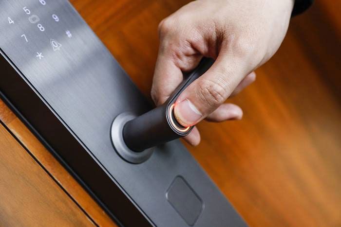
With the rapid development of science and information technology, intelligence has entered people's lives and brought great convenience to people's lives. The smart locks on the market include induction locks, fingerprint locks, etc. The functions of these smart locks are not perfect, and they also need to be improved in terms of humanization, because they are still relatively expensive for some dormitories or ordinary families, so they cannot be obtained. Wide-scale popularization, ordinary door locks are still used in many families, which brings a lot of inconvenience to people's lives. For example, people may lose their keys, and it is more cumbersome to open the door. The use of smart door locks can also play an anti-theft role, fully guaranteeing the safety of people's funds and property. This article analyzes the design strategy of mobile phone Bluetooth smart locks based on single-chip microcomputer systems.
1. Design scheme of mobile phone bluetooth smart lock based on single chip microcomputer system
1.1 Development Trend of Smart Lock
In order to improve the security of the system, it is possible to develop from a small number of mechanical keys to a large number of combination locks. Since the 1980s, the reliability and cheap products of electronic locks have also appeared, providing a new era for electronic locks to enter public life. Today, with the increasing development of science and technology, smart locks will develop better, mainly including the following points: 1) The security of electronic passwords continues to improve. 2) The set password can be modified according to your own situation. The advent of automatic password changes and multiple passwords keeps people's data protected. 3) The amount of passwords is increasing. The password of the key can be a number, an image, etc., so that the password resources of the electronic lock will be higher.
1.2 Bluetooth Smart Lock Design Scheme
Through the analysis of the Bluetooth lock, the minimum system of the hardware single-chip microcomputer, Bluetooth module, etc. should be used first, and the switch of the smart lock can be controlled by the mobile phone through Bluetooth. It is also necessary to have a certain understanding of the development of the Android system and learn the basic computer program JAVA Programming, C language, etc., realize the opening and closing of the lock, and pair the mobile phone with Bluetooth. After receiving the action command, the information is transmitted to the single-chip microcomputer, and the relay is controlled by analyzing the transistor control circuit to realize unlocking and closing. It is best to use a 220V household power supply and use a lithium battery as a backup power supply. The selection of single-chip microcomputer chips follows the following principles: 1) Use as many chips as possible, and reduce the number of peripheral devices. 2) The single-chip microcomputer chip should start from a technical point of view to ensure the safe and reliable operation of the system. At the same time, its practicality should also be considered from the perspective of the manufacturer. 3) Household power is used in this design to ensure that the Bluetooth cannot work due to power failure. In order to use 220V power supply to provide power, you can choose the following options: 1) Use switching power supply to convert 220V AC power to 5V DC power. Can't work long hours. 2) A transformer can be used to reduce the voltage. The circuit of the transformer is relatively stable and can ensure normal power supply. However, the system will stop working when the power is lost, and it should be restarted when the power supply is needed, resulting in data loss.
1.3 Overall debugging of the smart lock system
The debugging of the Bluetooth smart lock system includes three aspects: hardware circuit testing, overall system debugging, and software debugging: 1) Hardware circuit debugging. After the hardware circuit is made, it should not be powered on, and the individual components should be checked first, and then ensure that there is no problem in the connection and welding of the circuit, and there will be no short circuit, virtual soldering, etc. 2) Adjust the bluetooth module. It is necessary to check whether the circuit connection is correct. If you follow the designed circuit diagram, check step by step to see if there is any short circuit and whether the solder joints are firm. 3) The debugging of the software includes the syntax of the program itself and the function debugging on the circuit board. During the debugging process, errors should be eliminated, the corresponding version of the simulator should be configured, and then the mobile phone should be connected to the computer, and then start the following items Work, when there is no problem clicking each button, it proves that the design is correct. After ensuring that the debugging of each module is completed, it can run correctly. At this time, the module light of the smallest system lights up to ensure that the power supply of the single-chip microcomputer is normal. If the sign of successful connection is displayed, it means that the pairing is successful. And achieve the expected purpose.

2. Example of smart lock design and development
The smart lock system based on Bluetooth communication is based on ARM Cortex-M3 core embedded processor and Bluetooth serial port transmission protocol, and uses Bluetooth transmission control to realize a smart lock system with small size, low power consumption, flexible control and long life. The system combines single-chip embedded technology and wireless transmission technology, and uses mobile phone terminals to control the switch of the lock head. It is easy to operate, widely used, and safe in process.
The design selects STM32 single-chip microcomputer as the main control core of the system, which is composed of Bluetooth transmission module, lock terminal, relay module, pressure module, mobile phone APP terminal module and so on. The bluetooth module adopts HC-05 master-slave integrated bluetooth module to communicate with the single chip microcomputer and mobile terminal; the lock terminal adopts electronic access control 12V/24V small electric control lock; the relay module adopts 1-way 5V relay module with optocoupler isolation relay; The module adopts a high-performance boost (BOOST) module with 4A switching current. The whole system has low cost, high stability and low power consumption.
When in use, you can configure the Bluetooth module first, configure its baud rate and connection password, after the power is supplied, you can use the host computer software to connect, first enter the Bluetooth password to connect, after the connection is completed, enter a specific command, the host The computer sends the data to the Bluetooth module, and the Bluetooth module sends the data to the single-chip microcomputer. After the single-chip computer is processed, it controls the opening and closing of the relay through the IO pin, thereby controlling the switch of the lock. At the same time, after the execution of the command is completed, the information about the execution of the operation is returned to the host computer through Bluetooth transmission. The user interaction interface is relatively friendly, the system is stable, the power consumption is low, the safety is high, and the convenience is high, which can meet the needs of users.
3. Design process of smart lock scheme
3.1 The overall structure of the smart lock solution
The overall design of the smart lock based on Bluetooth communication consists of five modules: the minimum system module of the single chip microcomputer, the Bluetooth module, the relay module, the boost module, and the upper computer module. Its overall design can be divided into hardware design and software design: the hardware design is mainly the selection of functional modules and the design and connection of circuit diagrams, and the software design is mainly the writing of single-chip microcomputer programs and the writing of upper computer APP programs.
3.2 Smart lock hardware design
(1) Main control chip: The main control chip adopts STM32F1O3RCT6 single-chip microcomputer of STM32 series. The STM32 series is based on a special design for embedded applications that require high performance, low cost, and low power consumption. The core of STM32F103RCT6 is ARM32-bit Cortex-M3CPU, with a maximum operating frequency of 72MHz, up to 80 fast I/O ports, up to 3 USART interfaces, with sleep, shutdown and standby modes, and VBAT supplies power for RTC and backup registers. Because the chip has rich I/O ports and USART interfaces, high operating frequency, good real-time performance, low power consumption, stable working state and strong anti-interference ability, this chip is used.
(2) Bluetooth module: The Bluetooth module adopts HC-05 master-slave integrated Bluetooth module. When the Bluetooth device and the Bluetooth device are successfully paired and connected, we can ignore the internal communication protocol of Bluetooth and directly use Bluetooth as a serial port. When the connection is established, the two devices share a channel, that is, the same serial port. One device sends data to the channel, and the other device can receive the data in the channel. The HC-05 Bluetooth module is suitable for various 3.3V single-chip microcomputer systems. The module can use AT commands to set baud rate pairing, password user information, etc. The HC-05 module is a high-performance Bluetooth serial port module, which can be used for pairing with various intelligent terminals such as computers with Bluetooth functions, Bluetooth hosts, mobile phones, PDAs, and PSPs. Its baud rate range is 48001382400, and the module is compatible with 5V/ 3.3V microcontroller system. When the two Bluetooth modules in master-slave mode are successfully paired, it can simply replace the previous serial communication application and change to wireless Bluetooth.
(3) Relay module: The relay module adopts 1 channel 5V relay module with optocoupler isolation relay, which is triggered by high level. It does not light up when it is disconnected; when there is a high-level signal at the signal input terminal, the common terminal and the normally open terminal will be turned on; the relay can directly control various equipment and loads; there is a normally open and a normally closed contact; the relay contact capacity: 250V10A (AC) or 30V10A (DC) (theoretical maximum load capacity).
(4) Lock head: the lock module adopts electronic access control 12V/24V small electric control lock, which is wound by pure copper coil, small in size, stable in quality, durable, and has a service life of more than 500,000 times. The direction of the lock tongue can be changed at will , Optional DC12V/DC24V, I as the current: 800mA. This module has a built-in full copper coil, which can be energized and unlocked instantly, with low power consumption, simple structure, convenient installation, low cost of use, small size, light weight and strong applicability.
(5) Booster module: The system supply voltage is 5V, and the lock module’s opening voltage is DC12V/DC24V, so a booster module is needed to supply power to the lock module. The booster module in this design uses DSN6009, and DSN6D09 is a High performance boost (BOOST) module with 4A switching current. This module uses XL6009E1 of the second generation of high-frequency switching technology as the core chip, which has low cost and excellent performance.
3.3 Intelligent lock control program design
(1) The overall software implementation of the single-chip microcomputer: the execution flow of the overall program of the single-chip microcomputer is: the initialization of the advanced system (including the initialization of the clock, the initialization of the pin, the initialization of the relay, and the initialization of the serial port). First turn off the switch of the relay, then configure the baud rate and interrupt of the serial port, and then the system continuously checks whether it has received the information sent by Bluetooth. The level of the pin controls the switch of the relay, and then controls the switch of the lock head. If not, continue to detect.
(2) Android host computer program: The host computer program directly uses the Bluetooth serial port APP, which is a Bluetooth SPP (serial port) communication tool, which can connect to any Bluetooth device that supports serial port mode (such as mobile phones, single-chip microcomputers, etc.). The Bluetooth serial port can search for Bluetooth devices, supports Bluetooth client and Bluetooth server modes, has a keyboard view, can customize keys, can be set to ASCII or HEX display mode, and so on.
Summarize
For the purpose of application, this design has designed an embedded type product that meets the development trend of the times and is conducive to improving people's needs for family security and convenience. This application involves a wide range of knowledge, from the bottom to the top, and there are certain : PCB drawing and schematic design, MCU internal structure and peripherals, Cortex-M3 core, Bluetooth communication knowledge, communication protocol, C language, Java language, Android programming, etc. The vigorous development of embedded and Internet of Things has made the smart home industry represented by smart locks rapidly booming. This design uses STM32 single-chip microcomputer as the main control chip, mobile phone APP as the terminal, and Bluetooth module as the communication bridge. It is a huge market prospect. the design of. The system has good real-time and stability, strong concealment, strong battery life, and high security. It is one of the trends in the development of smart homes in the future.
The article mainly analyzes the design strategy of the mobile phone Bluetooth smart lock based on the single-chip system. It can be seen that in order to achieve the best design of the mobile phone Bluetooth smart lock, it is necessary to analyze the principle of the smart bluetooth lock, including the minimum system of the single-chip microcomputer, alarm Compare the circuit and other schemes, make a connection diagram according to the schematic diagram of the Bluetooth lock, realize the program of modifying the password, switching the lock, etc., achieve the overall debugging effect through software and hardware debugging, find the defects in the system, and finally realize the unlocking effect. so as to achieve the expected purpose.
The above are the details of the hardware design technology introduced by Shenzhen Zuchuang Microelectronics Co., Ltd. for you. If you have software and hardware function development needs for smart electronic products, you can rest assured to entrust them to us. We have rich experience in customized development of electronic products, and can evaluate the development cycle and IC price as soon as possible, and can also calculate PCBA quotations. We are a number of chip agents at home and abroad: Songhan, Yingguang, Jieli, Ankai, Quanzhi, realtek, with MCU, voice IC, Bluetooth IC and module, wifi module. We have hardware design and software development capabilities. Covering circuit design, PCB design, single-chip microcomputer development, software custom development, APP custom development, WeChat official account development, voice recognition technology, Bluetooth wifi development, etc. It can also undertake the research and development of smart electronic products, the design of household appliances, the development of beauty equipment, the development of Internet of Things applications, the design of smart home solutions, the development of TWS earphones, the development of Bluetooth earphone speakers, the development of children's toys, and the development of electronic education products.
Proposal recommendation
- TOP


