- Home >> News >> Blog articles >> Internet of things
Design of Photoelectric Intelligent Blind Guide
Eyes are an indispensable organ of our body and a window for human beings to understand the world and perceive the outside world. However, a simple walk is a luxury for the blind. This paper designs a photoelectric intelligent blind guide to help the blind to use the tactile perception of the pulse signal after simple training to help the blind to judge whether there are obstacles and whether they are away from them according to the frequency change. The distance and general orientation can achieve the function of guiding the blind.
1. Research plan
Using the principle of infrared ranging to measure obstacles at multiple points and transmit the obstacle information to the finger through the electric pulse signal, so that the user can roughly perceive the obstacle and its orientation through the sense of touch. When the sound switch is turned on, there will be a sound to prompt the obstacle position. (Figure 1)
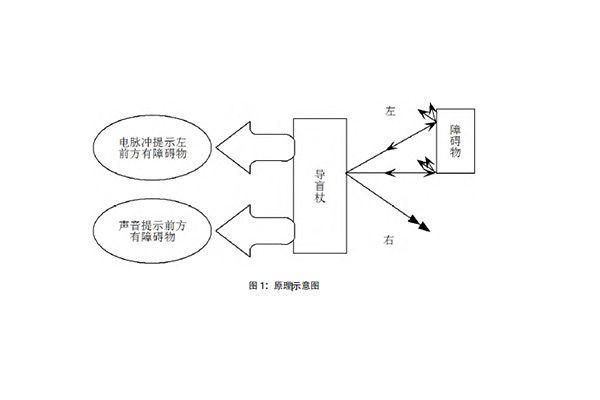
Due to the influence of detection distance and height, the measurement range of this system can be set within six meters. The working distance in close-range working mode is set to two meters and the working height is two meters, which can ensure that the user can perceive the existence of obstacles without shaking the instrument in a complex working environment.
The optical part adopts 850nm infrared LED light source, the output angle is 20 degrees, and the output distance of 1W power can reach 20 meters, which meets the coverage requirements of the measurement distance. The receiving device selects 850nm infrared receiving tube, and the receiving angle is controlled at 1 degree through the optical system. The electronic part can control the light source to send a pulse and start timing at the same time. When the receiver receives this pulse, the timing ends, and the single-chip microcomputer obtains the distance according to the time. The distance measurement equation: D=CT/2 (D is the measured distance, C is the speed of light , T is the time for the light pulse signal to go back and forth between the rangefinder and the reflected pulse of the target to be measured). The acquisition system will scan the corresponding angle of each receiver, and then transmit the data to the single-chip microcomputer for analysis, so as to calculate the distance and orientation of the obstacle, and finally transmit the information to the user through the pulse generator and the speaker.
2. Technical route and feasibility analysis
2.1 Optical part
Multiple 850nm high-power LEDs are used as light sources. The viewing angle of the light source is 44 degrees, forming a light curtain with a height of 2m at 5m, and a light curtain with a height of 1m at 2.5m (as shown in Figure 2). This working mode can be used in complex occasions.
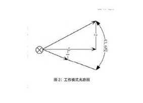
The receiver is an 850nm infrared receiver array, and each receiver receives for its own small field of view to improve the directivity of a single receiver and reduce the superimposed interference of optical signals. In the working mode of the light source, the receiving angle is mechanically changed for the viewing angle of the light source respectively.
2.2 Electronic part
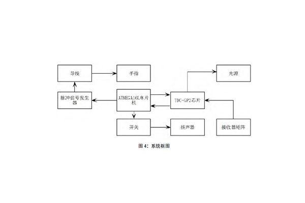
This system uses ATMEGA16L single-chip microcomputer as the controller to compare and analyze the receiver signals at each angle, and convert the analysis results into electric pulse signals for people to perceive (as shown in Figure 4). This system uses ATMEGA16L single-chip microcomputer as the main control chip. The single-chip microcomputer performs register configuration and time measurement control for TDCGP2, and the time measurement result is sent back to the single-chip microcomputer to calculate the distance accurately through the algorithm. Whether there is an obstacle in which direction is obtained through the measurement results, and the pulse generator generates a current signal to stimulate the finger, so that the blind person knows which direction there is an obstacle and which direction to avoid. Single-chip microcomputer control.
3. Conclusion
In this case, multi-point measurement is used, which improves the usability and provides a hint on how to avoid obstacles. Using current pulses to stimulate the finger as a prompt signal increases the amount of information compared to sound prompts and improves the reliability of information transmission.
Proposal recommendation
- TOP

