- Home >> Solution >> Electronics >> 3C digital
Wireless Charger Solution
With the continuous improvement of electrical equipment's requirements for power supply quality, safety, reliability, convenience, immediacy, special occasions, and special geographical environments, the contact power transmission method is increasingly unable to meet actual needs. Therefore, developing a wireless power transmission system with the advantages of wireless power transmission, high transmission efficiency, small size, portability and integration will become one of the most attractive scientific research directions in the 21st century.
1. Advantages of wireless charging over wired charging
Compared with the traditional charger method, the biggest advantage of wireless charging technology is that it avoids the use of charging wires. After adopting wireless charging technology, different electronic devices can adopt a unified wireless charging standard, and only one charger is needed to charge different devices. Another advantage of wireless charging technology is that it is non-contact. For electronic devices, the non-contact charging method does not require an exposed charging interface and can achieve a better waterproof design. The charger can also be embedded in the base of the lamp, the table or even the bedside table, which is convenient for users to charge anytime and anywhere.

2. Technical principle of wireless charging solution
Wireless power transfer technology was proposed by physicist Nikola Tesla in 1890. According to the different principles of power transmission, wireless power transmission can be divided into three methods: electromagnetic induction, electromagnetic resonance and electromagnetic radiation. As early as the 1920s and 1930s, some scholars have begun to discuss the possibility of the concept of wireless power supply. The real breakthrough in wireless charging technology occurred in 2007, when a research team at the Massachusetts Institute of Technology successfully lit a light bulb 2 meters away. With the continuous development and improvement of wireless charging technology, there are currently two mainstream technical routes: electromagnetic induction wireless charging and electromagnetic resonance wireless charging.
2.1 Principle of electromagnetic induction wireless charging
The principle of electromagnetic induction wireless charging is the same as that of a transformer. There is a coil at the sending and receiving ends. The coil at the sending end is connected to a wired power supply to generate an electromagnetic signal. The magnetic field of the wireless charging system is mainly transmitted through the air, so the magnetic field transmission efficiency is low. If you want the wireless charging efficiency of the system to reach more than 70%, the two coils need to be very close together, and the coils need to be similar in size, with precise positioning between the two, and this technology can only support one-to-one charging.
The electromagnetic induction wireless power transmission system usually uses a non-contact transformer coupling method for wireless power transmission. That is to separate the tightly coupled magnetic circuit of the transformer in the system. The primary winding of the transformer flows through high-frequency alternating current. Through the electromagnetic induction of the primary and secondary windings, the electric energy is transmitted to the secondary winding to supply power to the electrical equipment, realizing the power in the Wireless transmission between power source and powered device.
2.2 Principle of electromagnetic resonance wireless charging
The principle of the electromagnetic resonance scheme is the same as the resonance principle of the sound. The primary coil and the secondary coil achieve energy transfer through magnetic resonance. The transmitter oscillates at a specific resonant frequency, and adjusts the resonant frequency of the secondary coil to be consistent with that of the primary coil, thereby realizing energy transfer. The charging distance of the electromagnetic resonance scheme can reach more than 45mm, and the range is large, not limited to the planar structure. At the same time, one-to-many charging can be realized. The secondary coil at the receiving end can be configured in different sizes to adapt to different device power.
Electromagnetic resonance wireless power transmission systems usually use two resonators of the same frequency to generate strong mutual coupling, and use coils and plate capacitors placed at both ends to form a resonant circuit to realize wireless energy transmission. In June 2007, Marin Soljashik, an assistant professor of physics at the Massachusetts Institute of Technology, and his research team conducted an experiment to energize a coil with a diameter of 60cm, and the result was that it was connected to another coil 1.9m away. The 60W bulb on the coil was lit. This experiment shows that the coils at the sending end and the receiving end form a magnetic resonance system. When the magnetic field oscillation frequency at the sending end is the same as the natural frequency of the receiving end coil, the receiving end generates resonance, thereby realizing wireless transmission of energy. Its power consumption is only one millionth of the traditional electromagnetic induction power supply technology, and the effective transmission distance is tens of centimeters to several meters, so this transmission form is suitable for medium-range wireless power transmission.
2.3 Principle of electromagnetic radiation wireless power transmission
The electromagnetic radiation wireless power transmission system uses the microwave band for wireless transmission of electric energy. The electric energy is generated by the power supply, and the power frequency alternating current is converted into microwaves through the microwave converter, and then sent to space through the microwave transmitting antenna of the transmitting station, and then transmitted to the ground microwave receiving station, and the received microwaves are converted into power frequency through the converter Alternating current, for user use. Microwave is an electromagnetic wave with a wavelength between radio waves and infrared rays. Due to its high frequency, it can pass through the ionosphere without reflection. The universe is ideal for microwave transmission, and there is almost no energy loss. The loss when passing through the atmosphere is about 2%. , so the electromagnetic radiation wireless power transmission system has higher power transmission efficiency and is suitable for long-distance wireless power transmission.

3. Wireless Charging Technical Standards
In order to promote the application of wireless charging technology, communication operators, semiconductor companies and high-tech companies have formed different wireless charging alliances and launched their own wireless charging technology standards.
Currently the most mainstream wireless charging standard is the Qi standard launched by WPC (Wireless Power Consortium). The traditional Qi standard adopts an electromagnetic induction scheme. The Qi standard has good versatility and convenience. From homes, cars, to airports, cafes, and offices, the Qi standard supports a wide range of scenarios. Generally, wireless chargers with the Qi standard logo can supply power to electronic devices that support the Qi standard. In order to make up for the deficiency that the electromagnetic induction solution can only charge one-to-one, the latest Qi1.2 standard has added support for the electromagnetic resonance solution, which can realize simultaneous charging of multiple devices. Another wireless charging alliance, Airfuel, has also launched its wireless charging technology standards, including the PMA standard using the electromagnetic induction scheme and the A4WP standard using the electromagnetic resonance scheme. However, compared with the Qi standard, Airfuel is technically immature and has not been well applied commercially.
4. Design of electromagnetic induction wireless charger
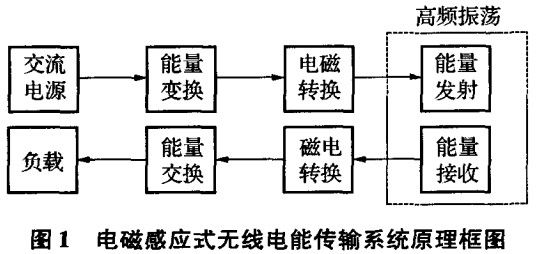
The schematic block diagram of a typical electromagnetic induction wireless power transmission system is shown in Fig. 1 .

The electromagnetic induction power transmission system is mainly composed of an energy conversion part, an energy transmitting part and an energy receiving part. The input alternating current is converted into direct current through rectification, filtering, and voltage stabilization, and is inverted by a high-frequency inverter. The high-frequency alternating current generated by the inverter is input into the primary coil of the separate transformer and coupled with the secondary coil, thereby generating The induced electromotive force is then filtered by high-frequency rectification to supply power to the load. In this paper, the main hardware circuit of the wireless charger designed using the principle of electromagnetic induction power transmission is shown in Figure 2.

4.1 Transmitter circuit design
The circuit is mainly composed of an oscillating signal generator and a resonant power amplifier. Use NE555 to form a signal generator with an oscillation frequency of about 400kHz to provide excitation signals for the power amplifier circuit; the resonant power amplifier is composed of an LC parallel resonant circuit and a switch tube Q1. When the resonant frequency of the frequency selection circuit of the power amplifier is the same as the frequency of the excitation signal, the power amplifier resonates, and the voltage and current in the coil reach the maximum value at this time, thereby generating the maximum alternating electromagnetic field.
4.2 Receiver circuit design
When the receiving coil is close to the transmitting coil, an induced electromotive force is generated in the receiving coil. When the resonant frequency of the receiving coil circuit is the same as that of the transmitting coil, the induced voltage reaches a maximum value. When both the transmitting coil loop and the receiving coil loop are in the resonance state, the system has the best energy transmission efficiency.
4.3 Charging circuit design
A charging circuit with 4 working modes of trickle current, constant current, overcharge and float charge is designed by using the power management chip. When the circuit is in the constant current charging mode, the charging current is set by the current detection resistor connected between the CSP pin and the BAT pin; Charging voltage. When the input voltage is too low, the charging circuit enters the sleep state. When the input voltage is greater than the starting voltage of 6V, the charging circuit starts to charge the battery. Divider resistors R6 and R7 feed back the voltage of the battery terminal to the FB pin of the chip, and the chip determines which charging mode to enter according to the voltage value fed back by the FB pin. When the voltage of the FB pin is close to 3.6V, the chip works in an overcharged state. If the battery voltage is lower than 81.8% of the set overcharge voltage, the charging circuit automatically enters the trickle charging mode, and the charging current is 13% of the set constant current charging current. When the battery voltage is greater than 81.8% of the set overcharge voltage, the charging circuit enters the constant current charging mode. The charging voltage set by the charging circuit designed in this paper is 5V, which can charge most electronic devices commonly used in life.
5. Shared wireless charger design scheme
When going out, the mobile phone has no power, which will bring various inconveniences to people's life. To solve the above mobile phone charging problems, a shared wireless charger design solution that is suitable for restaurants, cafes, railway stations, airports and other indoor public places and supports various mobile phones is needed. The shared wireless charging design scheme mainly includes four modules: wireless charging module, user interaction module, central control module and remote server module. The function description of each module is as follows.
(1) Wireless charging module: The wireless charging module is mainly responsible for realizing the charging function of the smartphone. There are currently two mainstream wireless charging technology routes: electromagnetic induction wireless charging and electromagnetic resonance wireless charging. Although the electromagnetic resonance wireless charging solution can support one-to-many charging and a longer charging distance, the electromagnetic induction wireless charging solution is more mature in technology and business. The Qi standard launched by the Wireless Power Consortium (WPC) is currently the most mainstream wireless charging standard. In the wireless charging module, we will also use a wireless transmitting coil that supports the Qi standard, so as to realize charging support for various mobile phones.
(2) User interaction module: The user interaction module is mainly responsible for the realization of the interaction function with users. In order to allow users to use our wireless mobile phone charger quickly and easily, we have adopted the user login method of scanning the QR code on WeChat. Users can directly use their WeChat account to log in to the mini program we provide, enter the number of the wireless charger around them, and obtain the permission to charge. After the user finishes charging, he can also pay the corresponding fee through WeChat payment and other methods.
(3) Central control module: The central control module is mainly responsible for communicating with the remote server and controlling the opening and closing of the wireless charging function. After the remote server successfully authenticates the user identity, it will send a corresponding message to the central control module. After the central control module receives the charging start information sent by the remote server, it will turn on the wireless charging function. After the remote server sends a stop charging message, the central control module will turn off the wireless charging function.
(4) Remote server module: The remote server module is mainly responsible for user identity authentication and fee calculation and other services. After the user logs in with the WeChat account, the remote server will query the corresponding information of the user in the database. When the user clicks the start charging and stop charging buttons in the WeChat applet, the remote server module will communicate with the central control module to turn on and off the wireless charging function. When the user finishes charging, the remote server will also calculate the corresponding fee.
The process of using the shared wireless mobile phone charger is as follows:
(1) The user scans the QR code on the desktop to log in to the WeChat applet.
(2) The user enters the number of the wireless charger around him, clicks the start charging button, and puts the mobile phone on the corresponding position on the table to start charging.
(3) After charging is complete, the user clicks the button to stop charging.
(4) According to the fee prompted in the mini program, the user completes the corresponding fee settlement through WeChat payment.
Summarize
This paper reviews the existing wireless charging technology routes and corresponding technical standards, and proposes a design scheme for a shared wireless mobile phone charger. Our design scheme combines the Qi wireless charging standard and various functions of WeChat software, which can provide a reference for future product design. A wireless charger is designed by using the principle of electromagnetic induction wireless power transmission. Tests show that the charger can realize high-efficiency transmission of electric energy within a short distance. Moreover, the charging circuit of the charger is more superior and advanced than the circuit given in the literature.
The above are the details of the wireless charger solution introduced by Shenzhen Zuchuang Microelectronics Co., Ltd. for you. If you have wireless charger technology development needs, you can trust us. We have rich experience in custom development of electronic products, and can evaluate the development cycle and IC price as soon as possible, and can also calculate the PCBA quotation. We are a number of chip agents at home and abroad: Songhan, Yingguang, Jieli, Ankai, Quanzhi, realtek, with MCU, voice IC, Bluetooth IC and module, wifi module. Our development capabilities cover PCB design, single-chip microcomputer development, Bluetooth technology development, software customization development, APP customization development, WeChat official account development and other hardware and software design. It can also undertake the research and development of smart electronic products, the design of household appliances, the development of beauty equipment, the development of Internet of Things applications, the design of smart home solutions, the development of TWS earphones, the development of Bluetooth earphone speakers, the development of children's toys, and the development of electronic education products.
- TOP
